
amplify voltage and build microphone circuit

An operational amplifier (op-amp) is a high-gain voltage amplifier with differential inputs and typically a single-ended output. It is widely used in various applications, including signal conditioning, filtering, and mathematical operations. The fundamental characteristics of an op-amp include high input impedance, low output impedance, and the ability to amplify small voltage differences between its input terminals.
In the context of creating a microphone circuit, the op-amp can be employed to amplify the low-level audio signals captured by a microphone. The basic configuration involves connecting the microphone to the non-inverting input of the op-amp, while the inverting input is connected to a feedback resistor network that determines the gain of the amplifier.
A typical microphone circuit using an op-amp may include the following components:
1. **Microphone**: A condenser or dynamic microphone that converts sound waves into electrical signals.
2. **Op-Amp**: An operational amplifier configured in a non-inverting configuration for voltage gain.
3. **Resistors**: Feedback and gain-setting resistors that control the amplification factor.
4. **Power Supply**: A dual power supply (positive and negative) is often required to allow the op-amp to output both positive and negative voltage swings.
5. **Capacitor**: A coupling capacitor may be added to block DC components while allowing AC signals (audio) to pass through.
The circuit diagram for this microphone amplifier would illustrate the connections between these components, indicating the input from the microphone to the op-amp, the feedback loop created by resistors, and the output which can be fed into further processing stages, such as additional amplification or audio processing circuits.
This configuration not only amplifies the audio signals for better clarity and volume but also allows for the integration of additional features, such as filtering unwanted noise or integrating with digital systems for audio analysis. Proper attention to component selection and circuit layout is essential to minimize noise and distortion in the amplified signal.An amplifier is something that amplified the voltage on a circuit. The most basic kind is an operational amplifier, and this video will show you how these work and how to use them in your electronics. As an example you`ll learn how to make a microphone circuit for spying on people or listening to your heartbeat.
Circuit Diagram.. 🔗 External reference
Related Circuits
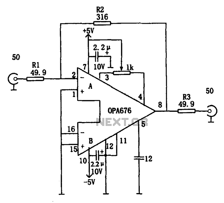
The circuit features a broadband video amplifier with a 50-ohm input/output impedance. To ensure optimal signal transmission and minimize reflected signals, it is often necessary to match the input and output impedances of the amplifier. The broadband video amplifier...
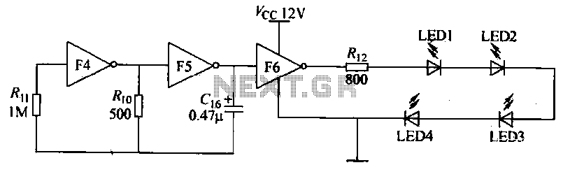
Gates F4, F5, and F6 together form a low-frequency oscillator that drives high-brightness light-emitting diode (LED) flashes. The light-emitting diodes may be arranged around the booth seat for decorative purposes. The automatic referral machine is used prior to operation...
A crystal oscillator circuit is a straightforward oscillator circuit that can be easily understood through its schematic diagram. It serves as a replacement for a conventional oscillator network, which typically consists of an LC combination. This simplicity is also...
This little guide for every electronics tester would actually have to lie in the toolbox. You can have components such as resistors, capacitors, diodes, etc. of testing. T1 and T2 form a Darlington. Therefore only need a small base...
This stereo noise blanker or suppressor attenuates noise by 45 dB when the music signal is low or absent; it functions primarily as a noise limiter. The noise blanker sensitivity... This circuit serves as a stereo noise blanker or suppressor,...

A digital stopwatch or digital timer circuit schematic is constructed using the timer IC LM555 and the 4-digit counter IC MM74C926, which is paired with a multiplexed 7-segment LED display. The digital stopwatch circuit utilizes the LM555 timer IC configured...