
SAA1042 stepper motor control circuit

The SAA1042 stepper motor driver operates with a supply voltage of 12V, making it suitable for applications requiring precise control of motor positioning. The selection of a 200mA phase winding current indicates that the motor is designed to operate efficiently at this current level, ensuring optimal performance while minimizing power consumption and heat generation.
The resistor RE, valued at 56kΩ, plays a crucial role in setting the appropriate biasing conditions for the driver circuit, ensuring stable operation and preventing excessive current draw that could lead to overheating or damage. The integration of the NAND gate MC14007 facilitates logic operations essential for controlling the stepper motor's direction and stepping sequence.
The clock signal, generated by the MC14046 and MC14024 PLL frequency synthesizer, is vital for the timing of the stepper motor's operation. By producing a frequency range of 12.5 to 500Hz, the system allows for a variety of stepping speeds, enabling users to select from seven distinct gear ratios. This flexibility is particularly beneficial in applications requiring different levels of torque and speed, enhancing the overall versatility of the stepper motor system.
The design exemplifies a well-integrated approach to controlling stepper motors, utilizing standard components to achieve reliable and efficient motor control in various applications, from robotics to automated machinery.A typical application example shown, SAA1042 12V stepper drive motivation, phase winding current is taken as 200mA. Choose from the RB Figure 5-10, taking RE = 56kfl. It is connected to the output of NAND gate MC14007. Figure 5-9 clock by MC14046 and MC14024 PLL frequency synthesizer composition produced. Stepping clock in 12. 5- SOOHz carve seven gear selection.
Related Circuits
This project involves a ding-dong doorbell circuit utilizing the 555 Integrated Circuit (IC). In a previous article, a simple doorbell circuit using the UM66 IC, a CMOS three-terminal melody IC, was discussed. The current circuit employs the NE555 IC...
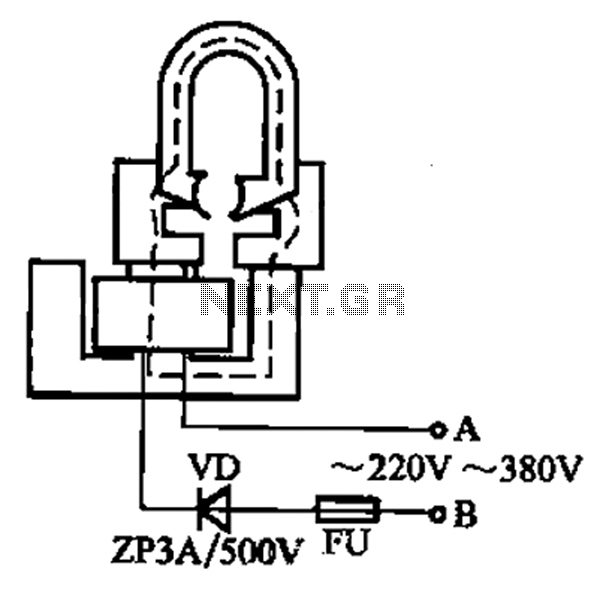
After a slight loss of field strength, magnets can be re-magnetized using a simple homemade porcelain filler. Locate scrap materials such as switches and contacts, as well as other models like CJ10-60 ~ 15. The circuit can operate at...

This circuit diagram of a digital clock utilizes six common anode seven-segment displays to indicate the time. It does not require microcontrollers or PICs for operation. The circuit operates using the MM5314 integrated circuit, functioning at either 50 Hz...
The circuit has been designed for telephone apparatus to indicate an incoming call as it rings using an LED for visual indication. BC550, an NPN general-purpose transistor, is utilized in the design. The circuit operates by detecting the ringing voltage...
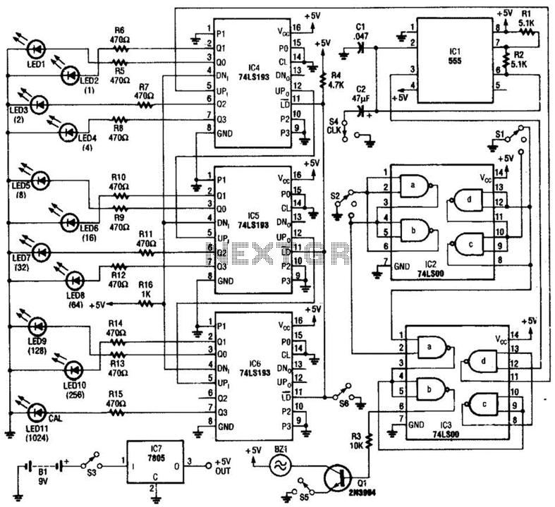
A diode, such as the IN4148, has a typical temperature coefficient of -2 mV/°C at a 1 mA diode current. Transistors Q1 and Q2 form a constant current source. Diode D1 serves as the temperature sensor. Integrated circuits ICl-a...

12V Battery Charge Nominal Discharge (Low) Indicator Circuit. This circuit monitors car battery voltage and provides an indication of nominal supply voltage, as well as low or high voltage. The 12V Battery Charge Nominal Discharge Indicator Circuit is designed to...