
High output 600 Ohm line driver

The described circuit operates under the principle of a floating output, which is crucial in applications requiring isolation from ground potential. The push-pull configuration of the current sources allows for efficient signal handling while maintaining high output impedance. This characteristic is particularly beneficial in applications where the load may not have a stable ground reference, such as in sensor applications or in environments with varying ground potential.
The use of operational amplifiers (op-amps) in this design enhances the circuit's performance by allowing for precise control of the output characteristics. The differential output impedance can be adjusted through the addition of a resistor between the non-inverting terminals of the op-amps, which balances the circuit without compromising the common mode performance. This balance is vital for minimizing distortion and ensuring signal integrity, especially in sensitive applications.
Resistor R7 plays a critical role in adjusting the common mode impedance, which can help stabilize the circuit when the load is floating. By carefully selecting the value of R7, the common mode impedance can be fine-tuned to prevent malfunctions that may arise from floating conditions. Furthermore, maintaining close tolerances on all resistors is essential to ensure that the circuit operates as intended and provides reliable performance.
The line driver’s capability to deliver +24 dB from ±12 V or +16 dB from ±6 V supplies indicates that the circuit is designed to handle a wide range of power supply configurations, making it versatile for various applications. The output gain levels suggest that the circuit can effectively drive loads while maintaining the desired signal amplitude, which is critical in communication systems and audio applications.
Overall, this circuit design exemplifies a robust approach to achieving a floating output while ensuring high performance and reliability across various operating conditions.The circuit has a "floating" output, i.e., it behaves like an isolated transformer winding, with the output amplitude remaining unchanged whether the center or either end of the load is grounded. This is achieved by making Z-out, common mode, infinite. The circuit consists of two current-sources in push-pull. Since each has infinite output Z, the common mode output impedance is also infinite. Connecting a resistor between the non-inverting terminals of the op amps reduces the differential Z-out without affecting the Z-common-mode.
Since the output is floating, if the load is also floating there is no output ground reference, which results in malfunction. This can be corrected by reducing the common-mode slightly. R7 fulfills this function. All resistors should be of close tolerance to give a good balance. The line driver provides +24 dB from ± 12 V or +16 dB from ±6 V supplies.
Related Circuits
The circuit below demonstrates how to power one or two LEDs from a 120-volt AC line. It utilizes a capacitor to reduce the voltage and a small resistor to limit the inrush current. As the capacitor needs to allow...
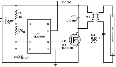
Whenever there is a need for battery-powered lighting, such as for camping, solar-powered cottages, cars, boats, planes, or emergency situations, fluorescent lamps are highly appealing. They are significantly more efficient than incandescent lamps, producing much more light for less...
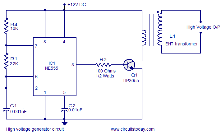
This circuit is highly dangerous due to its output voltage, which is in kilovolts and poses a significant risk of serious injury or death. It should only be attempted by individuals with extensive experience in handling high voltages. No...
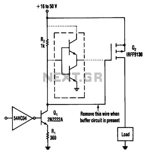
This circuit operates from a 16- to 50-V supply. Adding the buffer circuit (within the dashed lines) offers 100-ns switching times. Otherwise, the circuit switches in 1 µs. Q1 and R1 form a switched current source of about 12...
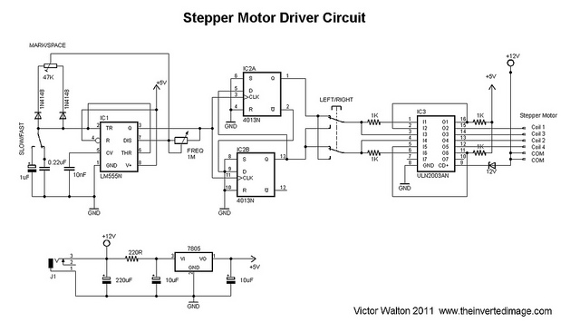
The commonly used 555 timer is configured for a variable mark/space ratio, which is essential for this application. Additionally, two D-type flip-flops (4013) are employed to provide the necessary count for the ULN2003 stepper motor driver. ULN2003 components may...
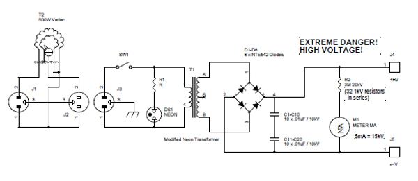
Transformers designed for powering large neon signs are cost-effective and highly reliable. Typically, the secondary winding is center-tapped, which restricts the full utilization of its peak-to-peak output in scenarios where one terminal must be grounded. In the power supply...