
microcontroller complete code midi emulated ps 2 keyboard

The described circuit is designed to interface with MIDI devices using a USART (Universal Synchronous Asynchronous Receiver Transmitter) for data reception and processing. The primary function of the circuit is to receive MIDI messages, specifically "note on" messages, which are identified by examining the first byte of the incoming data. This byte is masked to isolate the relevant bits, allowing for the determination of whether it corresponds to a MIDI "on" message.
Upon receiving a valid MIDI "on" message, the next byte of data is processed through a lookup table, converting it into a format suitable for transmission. The output is then sent through RA0 and RA1 pins, which emulate the behavior of a PS/2 keyboard, enabling the circuit to communicate with devices that expect keyboard input.
The implementation of diagnostic LEDs serves as a feedback mechanism for troubleshooting the circuit. LED1, which remains constantly on, may indicate an issue with the power supply or configuration settings. LED2's flashing behavior followed by a constant state could suggest intermittent operation or a fault in the code execution. The failure of LED3 to illuminate at all may point to a complete malfunction in that segment of the circuit or an error in the configuration settings.
The configuration settings provided are critical for the operation of the microcontroller within the circuit. These settings include disabling various features such as code protection (_CP_OFF), watchdog timer (_WDT_OFF), and enabling the high-speed oscillator (_HS_OSC), which are essential for ensuring reliable operation and performance of the system. Proper attention to these configurations is necessary to rectify the issues observed with the diagnostic LEDs and to ensure the successful transmission of MIDI data.hi i have been working on this code for a while now and i have come to a complete dead end. the following code takes midi data on the rx pin of the usart, saves the 3 bytes of data in the cblock, tests the first byte to see if it is a midi on message (xxxx1001) by masking the upper nibble and subtracting from a constant to see if it equals zero, i f so take the next byte, convert it using the lookup table. THEN send this data via ra0 and ra1 in a loop which emulates a ps/2 keyboard after calculating the odd parity bit. first things first, i wrote the diagnostic LED part which doesn`t work, led 1 is constantly ON and led2 flashes on, then off, then is constantly on, AND THEN led 3 won`t even come on.
_CONFIG _CONFIG1, _CP_OFF & _CCP1_RB0 & _DEBUG_OFF & _WRT_PROTECT_OFF & _CPD_OFF & _LVP_OFF & _BODEN_OFF & _MCLR_ON & _PWRTE_ON & _WDT_OFF & _HS_OSC 🔗 External reference
Related Circuits
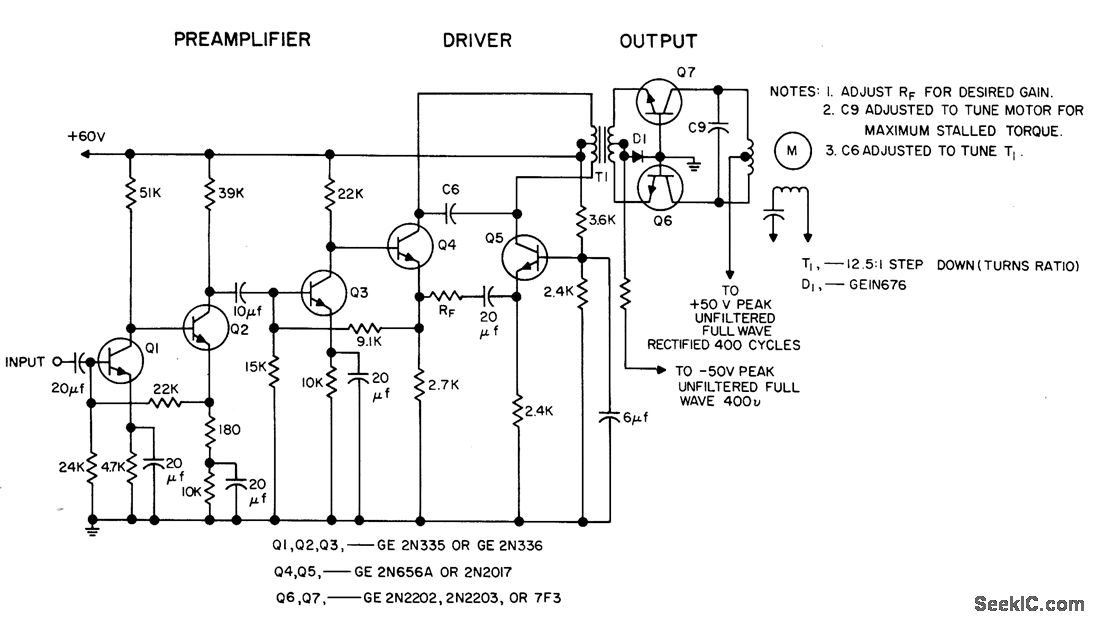
The circuit is capable of driving a 3W servo motor in an ambient temperature range of -55 to 125 degrees Fahrenheit, provided that capacitors rated for 125 degrees Fahrenheit are utilized. The gain can be adjusted over a range...
This article discusses the 128K EPROM (27C128), which was used in the 1986 to 1989 IROC-Zs equipped with the 1227165 ECM. The purpose is to provide a foundational understanding of binary and hexadecimal systems. Binary numbers consist solely of...
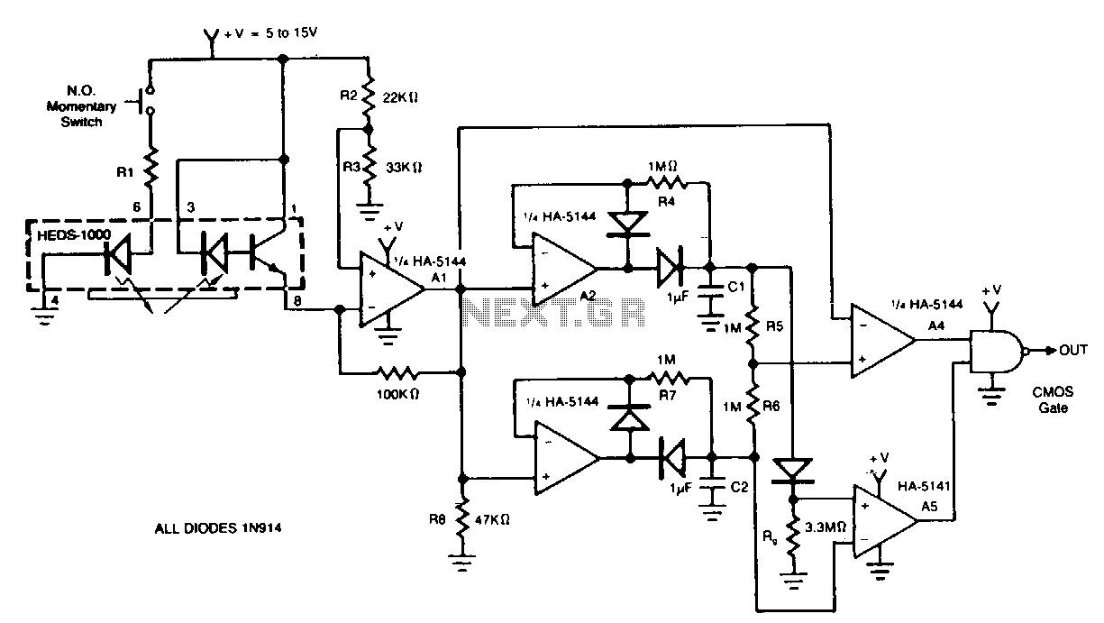
The circuit demonstrates a method for interfacing a HEDS-1000 emitter-detector pair with a HA-5144, intended for use as a barcode scanner circuit. The HA-5144 functions as an amplification system that transforms the widths of the printed barcode's bars and...
This project uses only a few of the instructions that come with PicBasic, but serves to show how easy PicBasic really is. It also shows how PicBasic strongly resembles programming the BASIC Stamp. Here we are using the serin...
This surround-sound decoder is based on the "Hafler" principle, first discovered by David Hafler sometime in the early 1970s. The original idea was to connect a pair of speakers as shown in Figure 1, for use as the rear...
CodeLock AVR electronic combination lock is realised with Atmel AVR microcontroller AT90S2313 or ATtiny2313. Program in hex code is 2 kB long. User code is consisted of 1 to 4 digits. If you buy the chip than user code...