
Microphone Amp

This sound detection circuit utilizes a condenser microphone as the primary sensor to convert acoustic signals into electrical signals. The microphone's output is typically a small AC voltage that represents sound waves. Following the microphone, an amplification stage is implemented to boost this weak signal to a more usable level. This is typically achieved using an operational amplifier configured in a non-inverting mode, which provides a gain determined by external resistors.
The amplified signal is then fed into a comparator, which compares the signal against a set reference voltage. The comparator is typically an integrated circuit like the LM393 or a similar device. When the amplified signal exceeds the reference voltage, the comparator's output switches from low to high, indicating that a sound has been detected. The reference voltage can be set using a voltage divider circuit, allowing for fine-tuning of the detection threshold.
Powering the circuit requires a stable voltage source, with options for either a 4.5 Volt or 9 Volt battery. The choice of power supply affects the output levels, with the 9 Volt option providing higher output voltage levels that may not be suitable for TTL logic applications. To adjust the sensitivity of the sound detection, a potentiometer is included in the circuit. This allows the user to control the gain of the amplification stage or set the reference voltage for the comparator, enabling the circuit to respond to various sound levels, from loud claps to soft whispers.
In summary, this sound detection circuit is versatile and can be integrated into various applications, including interactive robots and sound-activated devices. Its design emphasizes simplicity, allowing for easy assembly and modification to meet specific project requirements.This is a simple circuit that can detect sounds by using a common condenser microphone. Sensitivity is variable. The circuit`s output becomes High each time a sound is detected, otherwise it is in low level. You can use it in simple robots for sound responding (e. g. reaction -> when you clap your hands). This circuit recognize human voice as a co mmon sound (you can`t use it for voice recognition). The microphone stage captures the sound and converts it to electrical signal. The amplification stage amplifies the signal and the comparator changes the output level if the amplified signal is higher from the reference voltage. Also you will need a stabilized 5 Volt external power supply. You can use a 4. 5 Volt battery or even a 9 Volt battery. Be aware that with the 9 Volt battery the output level will be also at 9 Volt (not TTL logic). Attention: Vdd is the power supply (5 or 9 Volts). You can also use a 4. 5 Volt battery. You adjust the sensitivity by turning the pot. The circuit can be extremely sensitive and can detect low sounds or even whispers. 🔗 External reference
Related Circuits
A simple preamplifier circuit is often required, utilizing a few components for ease of construction. This circuit employs an operational amplifier, specifically the Motorola TCA5550, which features a dual amplifier configuration. It provides outputs for adjusting volume, balance, treble,...
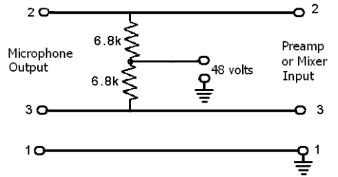
These devices require power to operate. This power can be supplied by a battery inserted into the microphone, a separate dedicated power supply with a specialized multi-pin cable, or most commonly, phantom power. Phantom power is supplied by a...
This circuit deactivates an amplifier or other devices when a low-level audio signal at its input is absent for at least 15 minutes. By pressing P1, the device is activated, supplying power to any appliance connected to SK1. The...
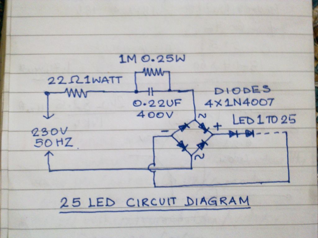
This circuit operates 25 LEDs powered by a mains supply of 230V. A fluorescent lamp adapter was acquired from a scrap dealer for ease of disassembly. The circuit consists of a series of 25 light-emitting diodes (LEDs) arranged to operate...
This assembly is designed for amateurs who possess a collection of vinyl records and wish to convert them into a digital format on a personal computer. Alternatively, they may want to enjoy an old, cherished LP collection through their...
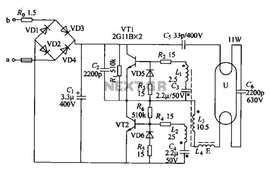
Energy-saving lamps are categorized into self-ballasted compact types and single-ended structures. They can also be classified based on appearance into various forms such as double-tube, four-tube, six-tube types, and others. The lifespan of energy-saving lamps is approximately ten times...