
speaker to microphone circuit converter

The circuit operates on the principle of electromagnetic induction, where the movement of the speaker diaphragm in response to sound waves creates variations in the magnetic field surrounding the coil. This results in an alternating current (AC) voltage that can be harnessed as an audio signal. The speaker, originally designed to convert electrical signals into sound, is repurposed to perform the opposite function—capturing sound and converting it back into electrical signals.
The key components of the circuit include the speaker, a transistor, and passive components such as resistors and capacitors. The speaker acts as the input transducer, while the transistor functions as the amplifier, boosting the weak audio signal generated by the speaker.
The circuit may utilize a common-emitter configuration for the transistor, which provides significant voltage gain. A resistor is connected to the collector of the transistor to set the operating point and ensure proper biasing. Additionally, a coupling capacitor may be employed to block any DC component from the output, allowing only the amplified AC audio signal to pass through.
To enhance performance, a power supply circuit is included to provide the necessary voltage for the transistor's operation. The overall design must consider the impedance matching between the speaker and the transistor to maximize signal transfer and minimize distortion.
This circuit can be used in various applications, such as audio recording, communication devices, and sound sensing systems, showcasing the versatility of converting a speaker into a functional microphone through careful circuit design.This circuit is a circuit diagram to convert the speaker into the microphone. In principle When sound waves fall on the diaphragm of a speaker, there will be fluctuations in the coil and the induced voltage will be no small proportion. This induced voltage is usually very large and useful low. Here, the low voltage circuit using a transistor amplified to produce a reasonable output 🔗 External reference
Related Circuits
The Johnson 275 watt and Kilowatt Matchboxes are often seen as exaggerated and unfairly criticized. They are neither exceptional tuners nor poorly designed. The main drawbacks include the fixed coupling link and the fact that they are balanced voltage...
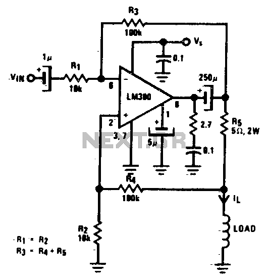
A low-cost converter is capable of supplying constant AC currents up to 1 A over variable loads. The low-cost converter is designed to provide a stable output of alternating current (AC) while accommodating fluctuating load conditions. This capability is essential...
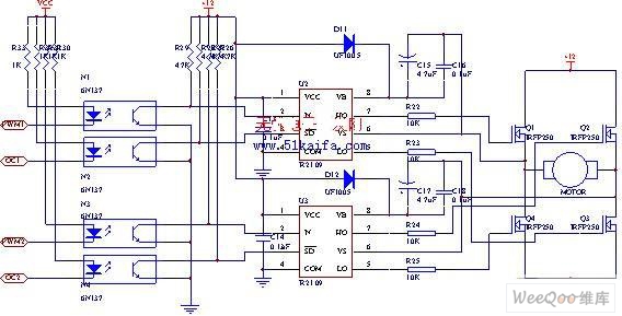
The drive circuit for the electromotor comprises a FET bridge circuit, a FET base drive circuit, a current sensor for the motor drive circuit, and a relay. The FET bridge circuit primarily consists of four high-power MOSFETs, which must...
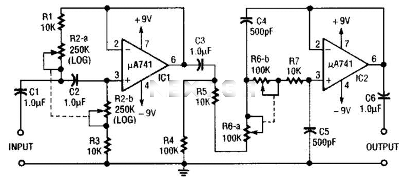
This circuit is a variable audio bandpass filter that features a low cutoff adjustable from approximately 25 Hz to 700 Hz and a high cutoff adjustable from 2.5 kHz to over 20 kHz. The roll-off is set at 12...
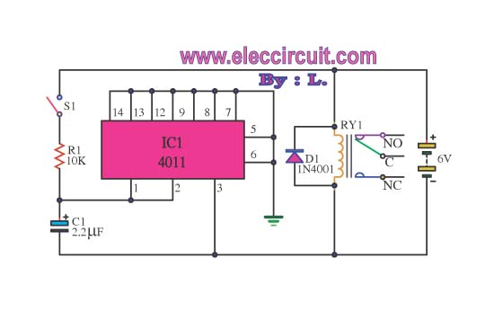
This circuit illustrates the use of the 4011 integrated circuit (IC) for a surge protection electronic circuit diagram. Features include the ability to delay the activation of other appliances connected to the output. The 4011 IC is a quad 2-input...
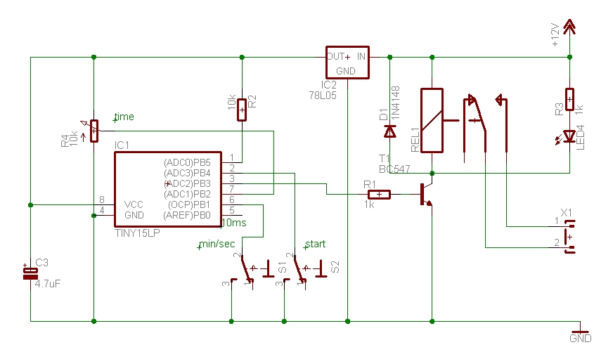
The time can be set using a potentiometer ranging from 1 minute to 1023 minutes, approximately 17 hours. A pushbutton initiates the timing process, activates a relay, and the timer will deactivate the relay once the set time has...