
microphone beyerdynamic TG X 50 Mk II

The TG X 50 Mk II microphone features a dynamic design optimized for capturing low-frequency sounds, making it particularly suitable for bass instruments and kick drums. The introduction of a passive equalization (EQ) filter in the Mk II model is a significant enhancement over its predecessor. This filter employs an LCR (inductor-capacitor-resistor) configuration, which is designed to attenuate specific frequency ranges rather than amplify them.
The passive EQ filter's design allows for a tailored frequency response, resulting in a pronounced mid-frequency scoop, effectively reducing levels by up to 7 dB between 100 Hz and 1 kHz. This scooping effect is beneficial for applications where clarity and punch are desired, such as in live sound environments or studio recordings. Additionally, the filter provides a 3-5 dB cut in frequencies above 4 kHz, which can help to minimize unwanted high-frequency noise and enhance the overall warmth of the sound.
The incorrect circuit schematic previously associated with the Mk II model did not accurately depict the presence of the passive EQ filter, leading to potential misunderstandings regarding its operational characteristics. The correct representation of the Mk II's circuit, as shown in the Opus 65 cutsheet, illustrates the integration of the LCR filter into the microphone's design, ensuring that users can fully leverage its capabilities. The literature emphasizes the importance of this filter in enhancing the microphone's performance, particularly in delivering deep bass and impactful kick drum sounds.
In summary, the TG X 50 Mk II's passive EQ filter is a critical feature that distinguishes it from the original TG X 50, providing a specialized frequency response that caters specifically to low-frequency applications.The Mk II was a second-generation version of the TG X 50. Both were dynamic microphones intended for bass instruments and kick drums. The primary difference between the two versions was the introduction of a passive EQ filter in the Mk II. Note that the circuit schematic (Schaltbild ) in the cutsheet linked from the right sidebar is incorrect
” it does not show the filter. The simpler schematic is this cutsheet is actually for the original TG-X 50, not the Mk II. The passive EQ filter circuit in the Mk II is pictured here (as diagrammed in the Opus 65 cutsheet). The Mk II`s EQ filter is an LCR circuit. As a passive circuit, it can only cut, rather than boost frequencies. Comparing frequency-response measurements of the TG X 50 and TG X 50 Mk II shows the effect of the resulting equalization: a broad mid-frequency scoop of up to 7dB, from 100Hz to 1kHz, and a 3 5dB cut above 4kHz. The Mk II literature describes this change: Durch ein spezielles Filter wird der Frequenzgang entzerrt, wodurch das Mikrofon mehr Tiefbass und Kick bekommt.
Roughly translated: Through a special equalization filter, the microphone produces more bass and kick. 🔗 External reference
Related Circuits
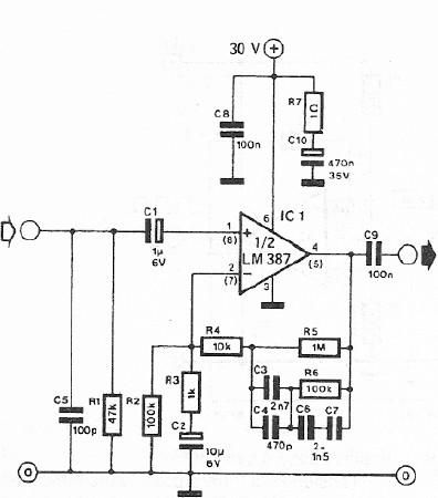
A dynamic microphone preamplifier can be constructed using the LM387 dual operational amplifier integrated circuit. The input impedance is approximately 47k ohms, primarily determined by resistor R1. If a dynamic microphone with a different impedance is to be connected,...
The circuit functions adequately, although it is not ideal in terms of quality. However, there is a minor issue when interfacing the output with an Arduino. The output swings below ground, meaning it is biased at 0V, while the...
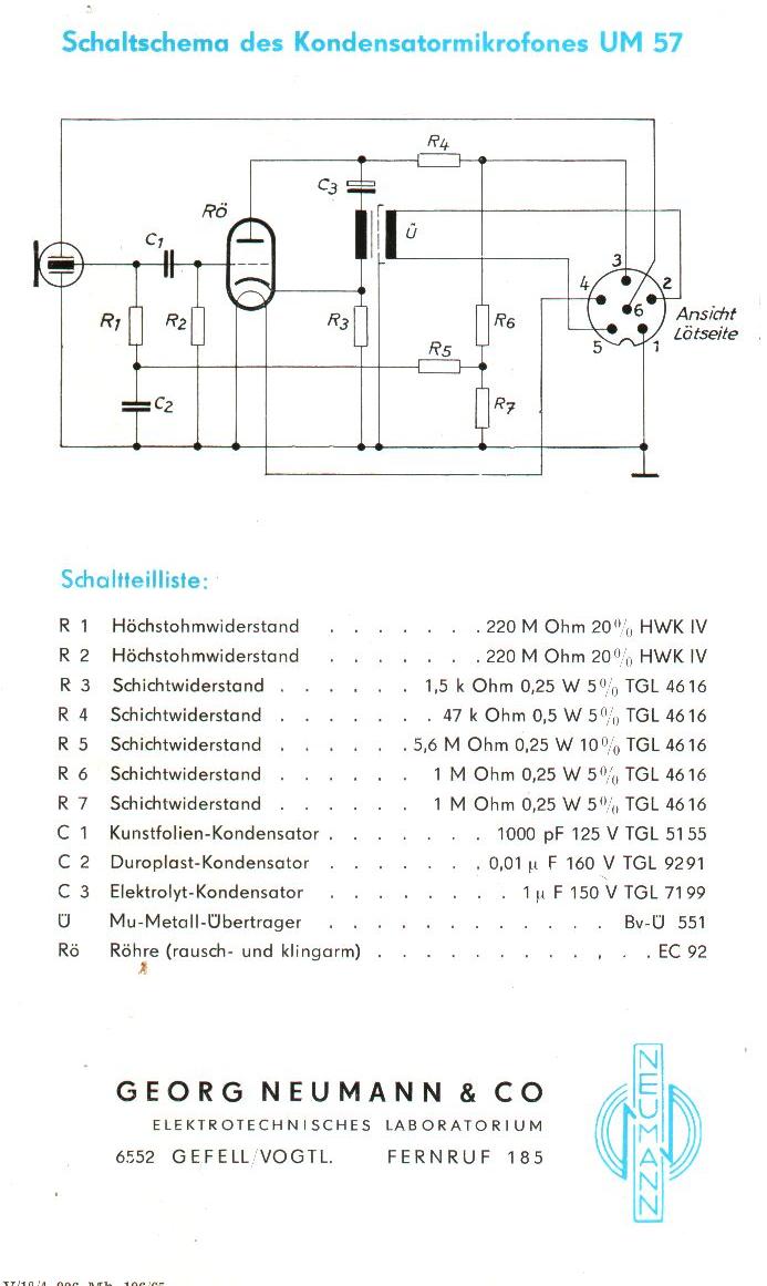
The Neumann/Gefell UM 57 is a large-diaphragm tube condenser microphone produced by the Neumann company in Gefell, Germany, now known as Microtech-Gefell. This microphone features the renowned M7 capsule from Gefell, which is a dual-diaphragm, center-terminated design with a...
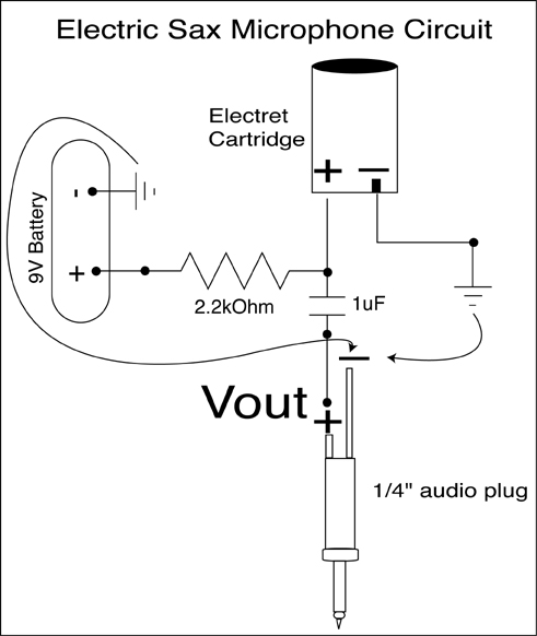
A condenser microphone (electret type with two terminals) is to be powered. A resistor of 1 kΩ and a capacitor of 10 µF have been connected to its positive terminal, while the other terminal is grounded. To power an electret...
This circuit is primarily designed to offer a microphone input for standard home stereo amplifiers. Utilizing a battery supply effectively eliminates the risk of low-frequency hum interference from the mains, and simplifies the connection to the amplifier by removing...
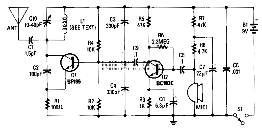
An adjustable capacitor C10 and a coil L1 create a tank circuit that, along with Q1, C2, and R1, oscillates at a frequency within the FM band. The center frequency is adjustable by tuning C10. An electret microphone, M1,...