
Micropower Clock

The described circuit utilizes a ceramic resonator as a clock source, which is advantageous for applications requiring low power consumption and low frequency. The design addresses the challenges posed by spurious resonance modes, which can interfere with the clock signal's integrity. By implementing a feedback mechanism, the circuit ensures that only the fundamental frequency of the resonator is utilized, enhancing stability and performance.
The circuit operates effectively across a wide temperature range, which is essential for applications in varying environmental conditions. The low power consumption of 2.8 mW makes it suitable for battery-operated devices, extending their operational life.
The arrangement of ICs within the circuit is critical. IC1A, IC1B, IC1C, and IC1D work in conjunction to create a robust feedback loop. The toggling action initiated by the rising edge of the resonator is reinforced by the AC-coupled feedback from IC1D, which prevents unwanted state changes that could be caused by external factors. This design feature is particularly important in maintaining the reliability of the clock signal.
The time constants associated with R2 and C2 are crucial in determining the response time of the circuit. By selecting values that constitute 60% to 75% of half the clock period, the design ensures that the circuit remains in a stable state until a valid transition is imminent. The choice of ceramic capacitors with a specific dielectric type ensures minimal variation in capacitance with temperature, further stabilizing the circuit's operation.
The parallel configuration of IC1D and IC1C serves to isolate the resonator from external influences, which is vital for maintaining signal integrity. This isolation prevents loading effects from external circuits that could distort the clock signal, thereby enhancing the overall performance of the system.
In summary, the circuit effectively leverages the properties of ceramic resonators while mitigating their drawbacks, resulting in a reliable and efficient clock source suitable for various low-power applications. Although ceramic resonators are a good choice for low-power, low-frequency clock sources (if you can stand their 30-ppm te mperature coefficient), they have troublesome, spurious-resonance modes. This circuit rejects all but the resonator"s fundamental mode. This clock circuit works from -40 to +80°C and consumes only 2.8 mW. The rising edge of resonator Y1 toggles IC1A low. ac-coupled positive feedback from IC1D via CI and RI immediately confirms this state change at IC1B so that Miller loading, harmonic components, or below-minimum rise times at IC1A cannot force IC1C to relapse to its previous state. This tactic also applies to resonator Yl"s falling edge because IC1C, via C2 and R2, holds IC1B high.
Choose time constants iiCi, and R2C2 to be equal and ranging from 60 to 75% of one-half of the clock"s period. Ceramic capacitors (10% tolerance) with X7R dielectric work well. With these time constants, the logic will be locked and unavailable to the ceramic resonator until just before it executes a legitimate transition.
IC1D and IC1C are in parallel to isolate the resonator from external loads and, more importantly, from C2.
Related Circuits
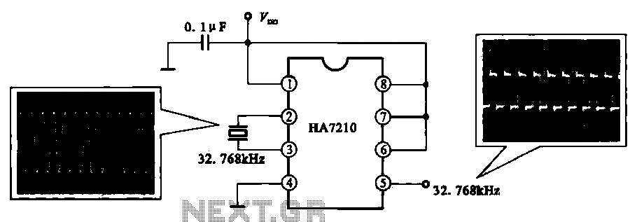
This circuit illustrates a 32.768 kHz micro-power clock oscillator, suitable for use in mobile phones, laptop computers, and home appliances. It generates a clock signal that can be utilized in various applications. The 32.768 kHz micro-power clock oscillator circuit is...
This is a programmable alarm timer circuit that uses LEDs to indicate hours and minutes. Twelve LEDs can be arranged in a circle to represent the 12 hours of a clock face, and an additional 12 LEDs can be...
The SI2171 is a sub-package of the SI2170. For further details, please refer to the SI2170 description. The datasheet for the SI2171 can be downloaded from the link provided below. By Silicon Laboratories. The SI2171 is a versatile integrated circuit...
Clocks have been discussed previously in relation to their interaction with flip-flops (FFs). It is important to note that a clock generates a timing signal used to control operations. This control mechanism is evident in both D and J-K...
The circuit utilizes 60 individual LEDs to represent the minutes of a clock and 12 LEDs to indicate the hours. The power supply and timing circuitry are consistent with those outlined in the previous 28 LED clock circuit. The...
This is a programmable clock timer circuit that utilizes individual LEDs to signify hours and minutes. Twelve LEDs can be arranged in a circular formation to represent the 12 hours of a clock face, while an additional 12 LEDs...