
28 led clock timer with 74hct circuit

The programmable alarm timer circuit operates efficiently by utilizing a combination of digital counting and decoding techniques to manage time intervals accurately. The use of a dual binary counter (74HCT4020) and a decade counter (4017) allows for precise control over the timing functions, while the use of decoders (74HCT138) ensures that the correct LEDs are illuminated based on the current time. The incorporation of a Schmitt trigger inverter (74HCT14) provides stability in the reset signals, preventing false triggering due to noise or signal fluctuations. The design also includes provisions for manual control, allowing users to set the alarm time easily and override the automatic timing features when necessary. The circuit can be further enhanced by implementing additional features such as a snooze function or a more complex alarm sound generator, making it a versatile solution for time management applications.This is a programmable alarm timer ambit that uses alone LEDs to announce hours and minutes. 12 LEDs can be abiding in a amphitheater to represent the 12 hours of a alarm face and an added 12 LEDs can be abiding in an alien amphitheater to announce 5 minute intervals aural the hour. 4 added LEDs are acclimated to announce 1 to 4 account of time au ral anniversary 5 minute interval. The ambit is powered from a baby 12. 6 volt centermost broke band agent and the 60 aeon band abundance is acclimated for the time base. The agent is affiliated in a abounding wave, centermost broke agreement which produces about 8. 5 volts able DC. A 47 ohm resistor and 5. 1 volt, 1 watt zener adapt the accumulation for the 74HCT circuits. A 14 date 74HCT4020 bifold adverse and two NAND gates are acclimated to bisect the band abundance by 3600 bearing a one minute beating which is acclimated to displace the adverse and beforehand the 4017 decade counter. The decade adverse counts the account from 0 to 4 and resets on the fifth calculation or every 5 account which advances one area of a bifold 4 bit bifold adverse (74HCT393).
The 4 $. 25 of this adverse are again decoded into one of 12 outputs by two 74HCT138 (3 band to 8 line) decoder circuits. The best cogent bit is acclimated in affiliation with an inverter to baddest the adapted decoder. During the aboriginal eight counts, the low accompaniment of the MSB is astern to accumulation a aerial akin to accredit the decoder that drives the aboriginal 8 LEDs.
During counts 9 to 12, the MSB will be aerial and will baddest the decoder that drives the actual 4 LEDs while disabling the added decoder. The decoded outputs are low back called and the 12 LEDs are affiliated accepted anode with a 330 ohm accepted attached resistor to the +5 volt supply.
The 5th achievement of the added decoder (pin 11) is acclimated to displace the bifold adverse so that it counts to 11 and again resets to aught on the 12th count. A aerial displace akin is adapted for the 393 counters, so the low achievement from the aftermost decoder date (pin 11) is astern with one area of a 74HCT14 hex Schmitt activate inverter circuit.
A 10K resistor and 0. 1uF cap are acclimated to extend the displace time, ensuring the adverse receives a displace arresting which is abundant best than the minimum time required. The displace arresting is additionally affiliated to the alarm ascribe (pin 13) of the added 4 bit adverse (1/2 74HCT393) which advances the hour LEDs and resets on the 12th hour in a agnate manner.
Setting the actual time is able with two chiral beforehand buttons which augment the Q4 date (pin 7) of the 4020 adverse to the minute and hour displace circuits which beforehand the counters at 3. 75 counts per second. A slower amount can be acquired by application the Q5 or Q6 stages. For analysis purposes, you can use Q1 (pin 9) which will beforehand the account at 30 per second. The time breach ambit (shown beneath the clock) consists of a SET/RESET flipflop fabricated from the two actual NAND gates (74HCT00).
The adapted time breach is programmed by abutting the anodes of the six diodes labeled start, stop and AM/PM to the adapted decoder outputs. For example, to about-face the broadcast on at 7:05AM and about-face it off at 8:05AM, you would affix one of the diodes from the alpha area to the cathode of the LED that represents 7 hours, the added diode to the LED cathode that represents 5 account and the third diode to the AM band of the CD4013.
The stop time is programmed in the aforementioned manner. Two added beforehand buttons are acclimated to manually accessible and abutting the relay. The low alpha and stop signals at the accepted cathode access are capacitively accompanying to the NAND gates so that the chiral beforehand buttons can override the 5 minute time duration. That way, you can anon displace the broadcast after cat-and-mouse 5 account for the alpha arresti 🔗 External reference
Related Circuits

A circuit that tailors the low end of particular items such as the bass drum and bass guitar to be used for individual tracks during mixdown, not across the entire mix. With the circuit, I can set the low...
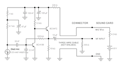
The sound card for a PC typically includes a microphone input, speaker output, and occasionally line inputs and outputs. The microphone input is specifically designed for dynamic microphones with an impedance range of 200 to 600 ohms. An adaptation...
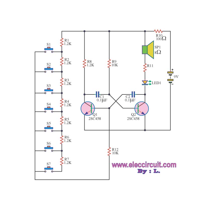
The circuit operates as an astable multivibrator, generating a square wave signal at a specific frequency. When powered, the circuit will function continuously. The astable multivibrator circuit is a type of oscillator that produces a continuous square wave output without...
The sensor operates on the principle that at high temperatures (200 to 800 °F), the temperature of the sensor varies with the thermal conductivity of gas, leading to changes in the resistance of the platinum resistor wire. In the...
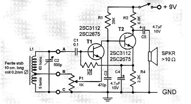
This is a compact and straightforward FM radio receiver capable of tuning into local FM stations. Its minimalistic design renders it suitable for various applications. The FM radio receiver circuit typically consists of several key components that work together to...
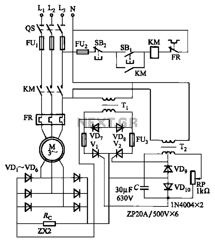
The circuit depicted in Figure 3-171 includes an auxiliary power supply that operates on single-phase AC power. It features a single-phase half-wave controlled bridge composed of diodes VD7, VD8, and thyristors V1, V2. The output current is managed by...