
microSD ATmega32 Data-Logger

The circuit design features an ATmega32 microcontroller at its core, interfacing with an 8-channel ADC to facilitate the collection of data from multiple sensors. The microcontroller is connected to a microSD card module, which handles data storage in FAT32 format. The microSD module is equipped with a voltage regulator and level converter to ensure compatibility with the ATmega32's 5V logic levels.
The LM35 temperature sensor is connected to one of the ADC channels, while the other channels are configured for voltage measurements from various sensors. The circuit includes a Real-Time Clock (RTC) module, which allows for accurate date and time stamps on the stored data. An RS232 interface is integrated for initial setup and debugging purposes, enabling communication with a PC.
LED indicators are incorporated into the design to provide visual feedback on power status and recording activity. A push-button switch allows the user to initiate or halt the data recording process. The recorded data is structured in a CSV format, with the first column indicating the date, the second column for time, and subsequent columns for sensor readings.
The circuit's operation is governed by firmware running on the ATmega32, which manages ADC conversions, data formatting, and file operations on the microSD card. The firmware handles the creation of new files based on the date and appends data strings to existing files as measurements are taken. This modular approach ensures that data logging is efficient and organized, facilitating easy access and analysis through software applications like Microsoft Excel.
Overall, this project exemplifies the integration of microcontroller technology with data storage solutions, enabling versatile sensor applications with user-friendly data management capabilities.Aim of this project is to present a way to store a large quantity of data into microSD card in files with FAT32 format. Here, ATmega32 is used for data collection and microSD interface. The data is received from in-build 8-channel ADC of ATmega32. One channel is used for reading temperature from LM35 sensor and remaining channels are used for simp
ly reading voltages and storing them. This project can be used to interface 8 different sensors with ADC of ATmega32, similar to the LM35 used here. The data is stored in CSV (comma separated values) format, which can be read using a PC/Laptop with Microsoft Excel or other compatible software.
A snapshot of the excel file is given later in this post. This project is an example of how to use the microSD FAT32 library presented in my earlier post. In that post, the files were created using hyper-terminal and entering data with the PC keyboard, since that demonstrates the file creation and it`s easy to debug. But many users have requested to make the file creation independent of the terminal, done inside the microcontroller, so I`m showing here how to use those functions independent of terminal.
If you have directly landed on this page, it would be more helpful if you visit the original post first as it would be a better starting place for learning SD or FAT32 functions. The project contains RTC interface (for date and time storage), RS232 (for connection with PC) and a microSD module.
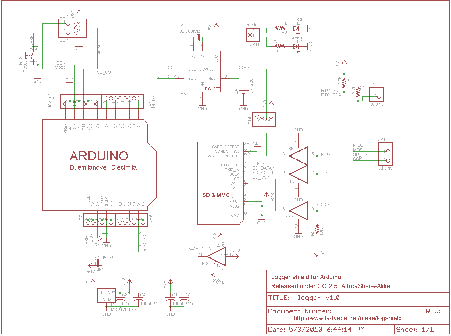
Here, the hyper-terminal connection is required only for setting RTC date and time. Once the date/time are set, the RS232 connection is not required anymore for normal data-logging operation (It can be used for debugging purpose if there is a problem). The module is shown in the figure here. Other than the microSD socket, this low-cost module also contains on-board 3. 3v regulator for the microSD card, a 5v-3. 3v level converter and other safety features required for the card. This module is used here as it provides a stable interface and makes the the card compatible with 5v supply and 5v signals of microcontroller.
The schematic also shows two LEDs and a push-button. The LEDs are used for indications of power and recording and the push-button is used to start-stop recording. The operation is very simple as it uses just one push-button and an LED indication. In case of any error in accessing the card, red LED will blink continuously. In such a case, you can start circuit in debug mode (with terminal) and see the error messages. Files are stored with the date as a name and. CSV extension. For example, data-logging done on 10 May 2011 would be stored in "10052011. CSV" file. Since the date is the name of file, everyday a single file is created and all the data recording done in a day goes into single file, no matter how many times the recording is stopped/started.
First column of the file shows date, second shows time and next 8 columns show data from the 8 channels. A file created during testing is shown in the figure below, where 5 sec interval was set for measurements (click on the image to enlarge it).
Here channel-0 was used for LM35 temperature sensor, and remaining channels measure voltage. 5v was connected to channel-1 and 3v Li cell was connected to channel-3 (Channel 2 & 4 show some small voltages due to noise from voltages connected to nearby channels, which can be corrected by using bypass caps). The interval between two measurement cycles is defined in main. c file, which can be set as per the user requirement. Basically, the program forms a dataString in every measurement cycle and appends this string to the file, if the file already exists or it creates a new file (for example, during the first recording in a day).
You may go through the comments in the source code file for more info. 🔗 External reference
Related Circuits
The board features a small power supply that generates 3.3V at 250mA. The built-in 3.3V regulator on the Arduino is not utilized because it is only guaranteed to provide up to 50mA, which may not be sufficient for some...
A basic introduction to RS232-based serial communication on the ATmega32/16 using the USART hardware. It is recommended to have the ATmega32 datasheet available for reference. Serial communication involves transmitting data one bit at a time across a communication channel,...
This circuit is a church bell controller. Basic component is an ATmega32 microcontroller. At the circuit 1 24LC32 EEPROM memory is being used. As control, a menu is created that appears on a 4x20 LCD (Liquid Crystal Display). The...
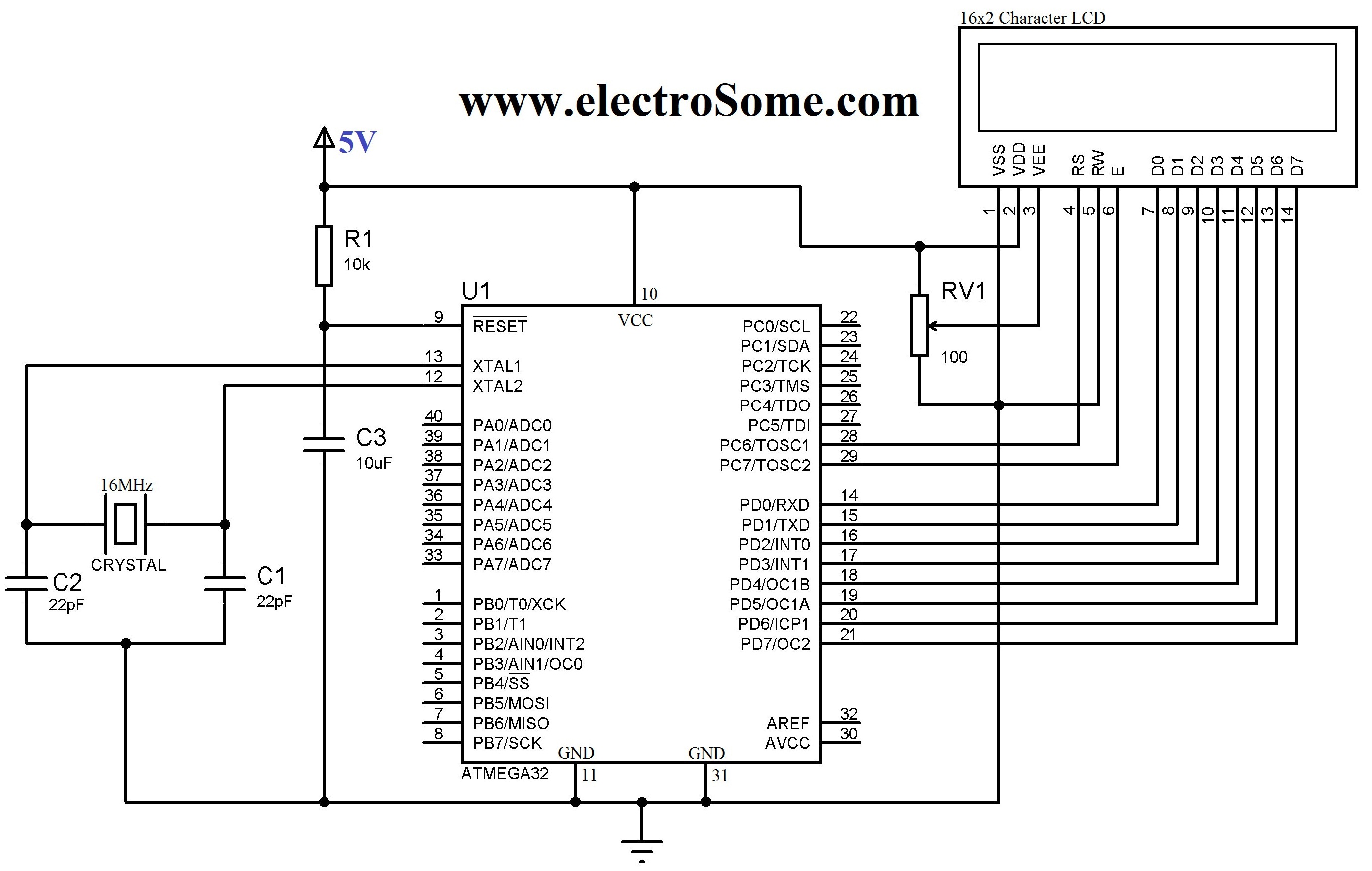
An LCD (Liquid Crystal Display) is a widely used electronic display found in devices such as calculators, laptops, tablets, and mobile phones. The 16G-2 character LCD module is a fundamental component frequently utilized by electronics enthusiasts and integrated into...
This article discusses the Gadgets, Gizmos, and Arduino (ATMega328). The content is straightforward and informative. The components mentioned in this article can enhance the understanding of the subject. For instance, readers can find and purchase components such as the...
Detecting the color of an object can be an interesting and useful electronic application. This can be achieved using a color sensor like the TCS3200 in conjunction with a general-purpose microcontroller such as the AVR ATmega32. The TCS3200 chip...