
Microwave Inverter

The Panasonic microwave inverter is a sophisticated component designed to provide precise control of microwave power output. This inverter operates by converting direct current (DC) into alternating current (AC), which is essential for the functioning of microwave ovens. The inverter technology allows for varying the power levels efficiently, in contrast to traditional microwave ovens that utilize a straightforward on/off cycling method.
In a typical application, the inverter module takes a DC input, often derived from a high-voltage power supply, and converts it to a high-frequency AC output. This output is then fed into the magnetron, which generates microwaves for cooking or heating food. The inverter's ability to control the power output smoothly allows for more even cooking and defrosting, as it can maintain a consistent temperature without the fluctuations associated with conventional microwave systems.
For integration into a project, it is essential to ensure that the inverter is correctly interfaced with the power supply and the load (magnetron). Adequate safety precautions must be taken due to the high voltages involved. Additionally, understanding the inverter's specifications, such as input voltage range, output frequency, and power ratings, is crucial for successful implementation.
The inverter circuit typically includes components such as capacitors, inductors, and control circuitry that regulates the switching of the power transistors. This switching mechanism is often driven by a microcontroller or dedicated control IC, which can be programmed to adjust the output based on user input or predetermined cooking profiles.
In summary, the Panasonic microwave inverter presents a valuable opportunity for experimentation in power control applications, provided that the user adheres to safety standards and possesses a fundamental understanding of electronic principles.Hi, I am trying to use a Panasonic microwave inverter for a project I am experimenting with. I have limited knowledge with electronics but I can work.. 🔗 External reference
Related Circuits
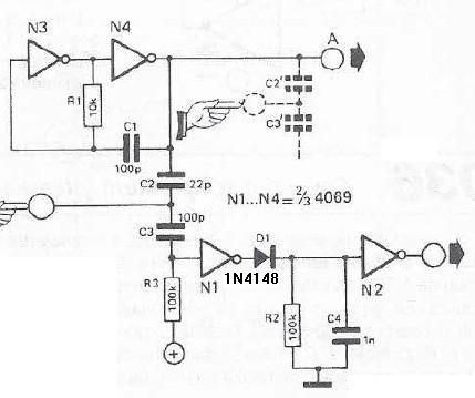
This touch sensor switch is designed using inverters (N1, N2) and several common electronic components. In the standby state, a signal is produced by the oscillator N3/N4 at the inputs of N1. When the touch sensor is activated, the...
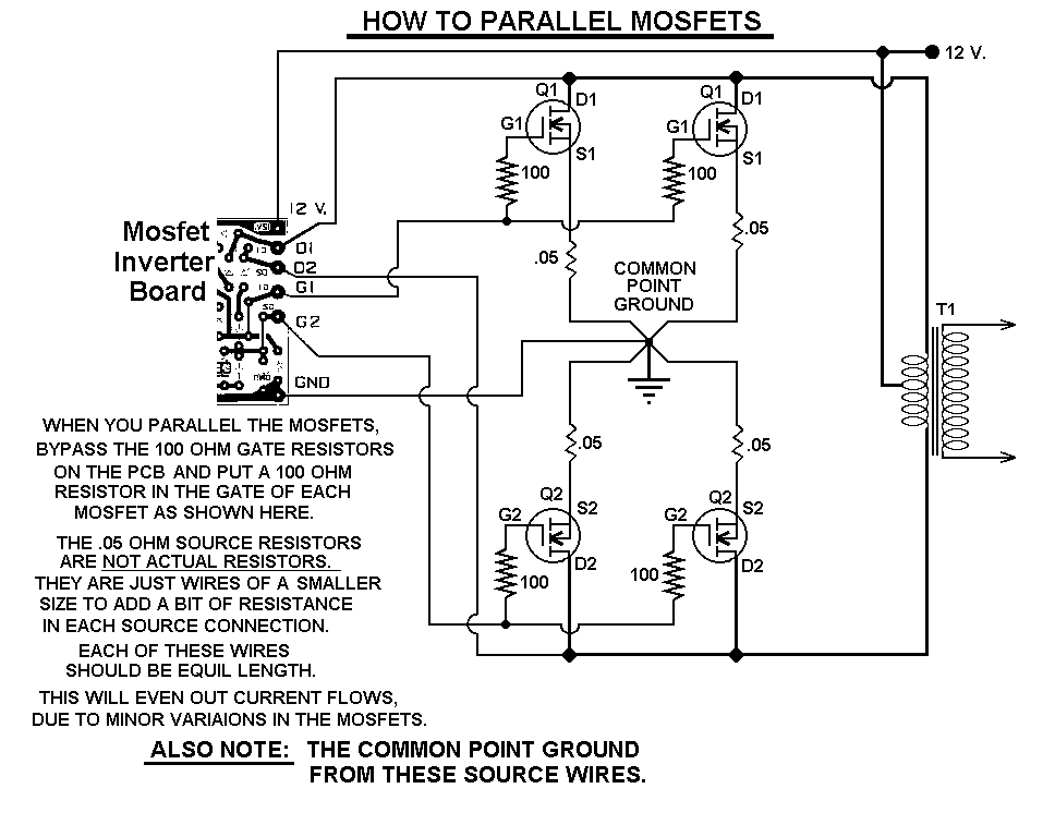
This 1000-watt power inverter circuit diagram is based on the MOSFET RF50N06. For increased power output, additional MOSFETs can be paralleled with the RF50N06. These MOSFETs are rated for 60 volts and 50 amps. It is essential to connect...
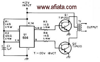
The first section of the 555 timer is configured as an astable oscillator, with R2 and C1 determining the frequency. The output is accessible at pin 5. The second section functions as a phase inverter, with its output available...
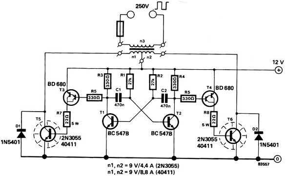
A power inverter converts direct current (DC) power to standard alternating current (AC) power. The following schematic illustrates a 12V power inverter circuit diagram. The 12V power inverter circuit typically consists of several key components that work together to achieve...
A guide for creating a remote power switch for a DC to AC inverter. The purpose is to enable the user to turn the inverter on and off remotely. The design of a remote power switch for a DC to...
This inverter is designed to operate fluorescent lamps ranging from 8W to 20W, with optimal performance achieved using 16W tubes. It preheats the electrodes and maintains their temperature during operation. The inverter functions by converting direct current (DC) into alternating...