
MIDI Controller Footpedal

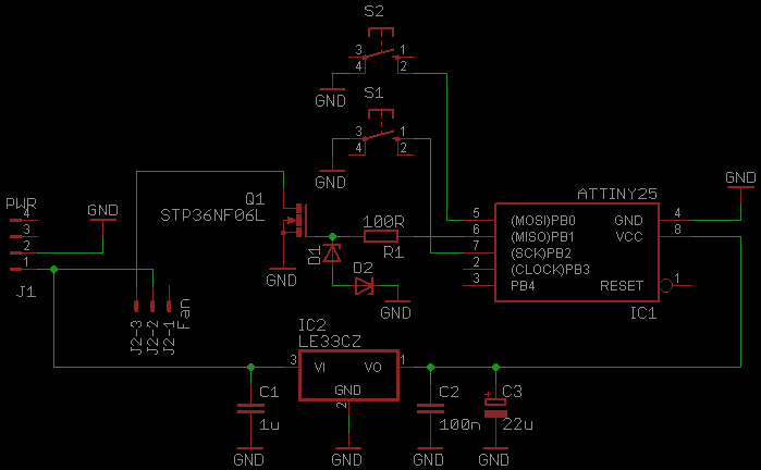
The MIDI controller pedal described serves as an interface for musicians to manipulate MIDI data in real-time, translating the physical position of a potentiometer into MIDI control changes. The circuit typically consists of a potentiometer, microcontroller, MIDI interface, and a panic button.
The potentiometer acts as an analog input device, translating the user's foot movement into a variable resistance that is read by the microcontroller. The microcontroller, programmed to interpret the potentiometer's output, converts the varying voltage levels into corresponding MIDI messages. These messages can be continuous controller messages (CC) or switch messages, depending on the configuration of the potentiometer and the desired output.
To construct the MIDI controller pedal, the following components are necessary:
1. **Potentiometer**: A linear or logarithmic potentiometer (typically 10kΩ to 100kΩ) is used to control the MIDI data. The choice of potentiometer affects the response curve of the pedal.
2. **Microcontroller**: A suitable microcontroller, such as an Arduino or a dedicated MIDI controller chip, is used to process the analog signals from the potentiometer and output MIDI messages via a serial interface.
3. **MIDI Interface**: This can be a standard 5-pin DIN connector or a USB output, allowing the pedal to connect to other MIDI-capable devices.
4. **Panic Button**: A momentary push button connected to the microcontroller that, when pressed, sends a MIDI "All Notes Off" message to silence any notes that may be stuck due to transmission errors or other issues.
The circuit design should include power supply considerations, typically using a 9V battery or an external power adapter. Proper grounding and shielding techniques should be employed to minimize noise and interference, especially in live performance settings.
The enclosure for the pedal can be constructed from durable materials to withstand foot traffic, and the layout should allow for easy access to the panic button and potentiometer while ensuring stability during use.
In summary, this MIDI controller pedal provides musicians with a versatile tool for real-time MIDI manipulation, enhancing live performances and studio sessions alike. The incorporation of a panic button adds a layer of reliability, ensuring that performers can quickly address any issues with stuck notes.Here`s a simple project that sends continuous or switch controller MIDI messages that correspond to the position of a potentiometer. Given a few parts and a cannibalized volume or wah-wah pedal, you can build this MIDI controller pedal and have the ultimate source of controller data in the Universe.
This pedal is especially useful in live performance, but it`s also great to have around when sequencing. An added bonus: the MIDI Footpedal sports a panic button that will silence any stuck notes that come your way.
🔗 External reference
Related Circuits
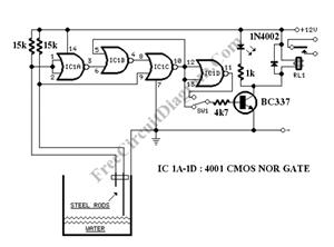
The circuit consists of a 555 timer IC configured as a multivibrator, which operates with two probes to measure the water level. When the capacitance between the probes indicates a high water level, the output from the 555 timer...
The 4017 traffic light circuit connects four legs to the green LED and two legs to the amber LED. This configuration raises the question of whether it could function with only one leg per LED. Each output is activated...
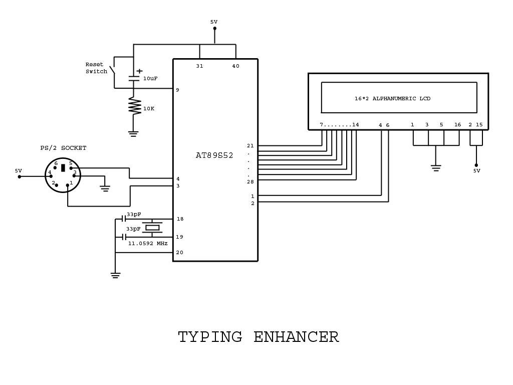
Project with Circuit and Code for a Typing Assistant using the 8051 microcontroller (AT89S52) and the PS/2 keyboard port of a computer. The project also explains the interfacing of the PS/2 port of a computer with the 8051 microcontroller. The...
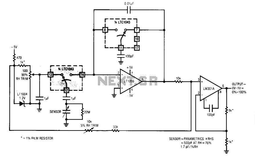
When the 14B-12B pair opens, 12B is connected to Al's summing point via 13B. The sensor now discharges into the summing point through the 1 µF capacitor. Since the charge voltage is fixed, the average current into the summing...
This document serves as a continuation of the previous work on PWM controllers utilizing 555 timers. The new design incorporates microcontrollers and MOSFETs in place of the 555 integrated circuits and transistors. Two versions have been developed: one equipped...
The 8051 microcontroller features a transmit channel and a receive channel for serial communication. The transmit data pin (TXD) is designated as P3.1, while the receive data pin (RXD) is located at P3.0. The serial signals on these pins...