
Dual Tone Model Train Horn/Sound Generator Circuit using 556 IC

The circuit utilizes the NE 556 IC to generate two distinct tones that can simulate the sound of a model train horn. The NE 556 is advantageous in this design as it reduces the number of components required, simplifying the layout and minimizing space on the circuit board.
In this configuration, the NE 556 is set up in astable mode, where each timer generates a square wave output at a specific frequency. The first timer produces a lower frequency tone, while the second timer generates a higher frequency tone. The output from both timers is combined using a simple resistor-capacitor network, which blends the two tones to create a more realistic horn sound.
The frequency of the tones can be adjusted by changing the resistor and capacitor values connected to each timer. This allows for customization of the sound produced to match the desired characteristics of the model train horn. Additionally, the output can be connected to a small speaker or piezo buzzer to produce audible sounds.
Power supply considerations for this circuit typically involve a DC voltage source ranging from 5V to 15V, which is suitable for the NE 556's operating range. Proper decoupling capacitors should be placed near the power pins of the IC to ensure stable operation and minimize noise.
Overall, this dual-tone sound generator circuit is an effective and efficient way to simulate the sound of a model train horn, providing an engaging auditory experience for model train enthusiasts.A dual tone model train horn/sound generator/simulator circuit can be made using two NE 555 timers connected in cascade. But here circuit diagram is designed with NE 556 IC, which is nothing but two 555 in one package.. 🔗 External reference
Related Circuits
This circuit is a simple mixer circuit that can mix two signal channels into one output channel. It utilizes a codec circuit to convert stereo audio into mono audio. Additionally, the circuit can increase the number of channels by...
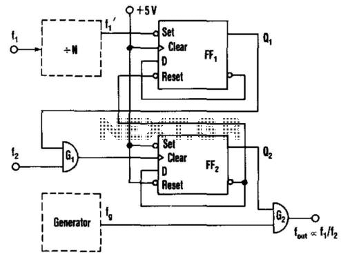
This circuit generates an output frequency that is linearly proportional to the ratio of two input frequencies. Each pulse of the bias frequency will open a switch for a period equal to half of the second input frequency, allowing...
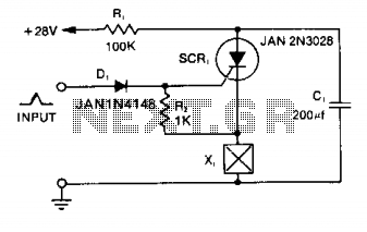
Capacitor C1 is charged to +28 V through resistor R1 and stores energy for firing the squib. A positive pulse of 1 mA applied to the gate of SCR1 will cause it to conduct, discharging C1 into the squib...
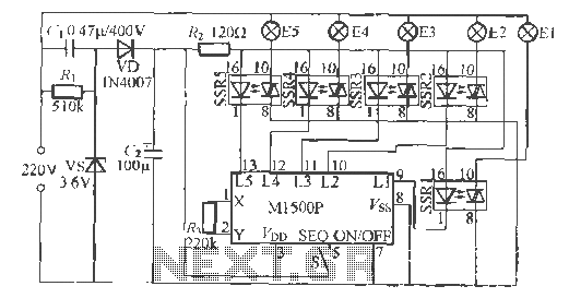
The Shenzhen Skywave Semiconductor Co., Ltd. produces a five-flash integrated circuit controller known as M1500P. This device is manufactured using a DIP 14 standard package and can be customized according to customer specifications for soft seal packaging. It operates...
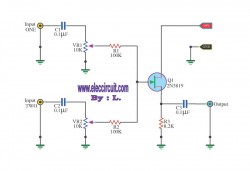
This circuit allows the use of an inexpensive loudspeaker as a microphone. Sound waves that reach the speaker cone cause fluctuations in the voice coil. The movement of the voice coil within the speaker's magnetic field generates a small...
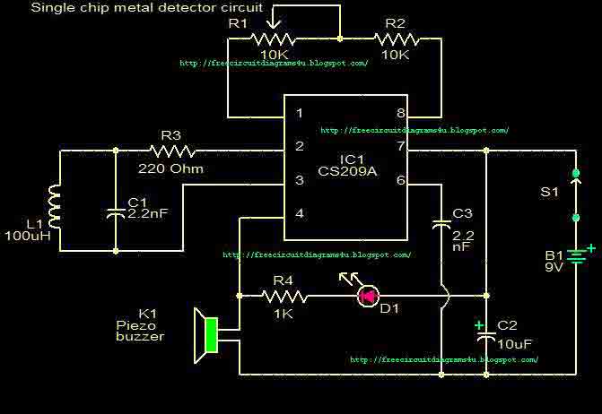
This circuit is a single chip metal detector. Actually, we can use this one to detect metals. Especially, you have seen some army soldiers keep something to detect metals. That equipment has been made through this circuit. So you...