
Mini High-Voltage Generator

The circuit operates on the principle of a Hartley oscillator, which consists of an inductor and a capacitor forming a resonant tank circuit. The transistor serves to amplify the oscillations generated by the tank circuit. When the circuit is powered, the transistor begins to switch on and off, creating alternating current (AC) at a specific frequency determined by the values of the inductors and capacitors in the circuit. The center-tapped transformer plays a crucial role in stepping up the voltage for practical use while ensuring that the circuit remains compact.
The output stage of the circuit is critical for ensuring safety and functionality. The inclusion of current-limiting resistors R2 and R3 prevents excessive current from flowing through the load, reducing the risk of electric shock. The design must adhere to safety standards, as the high voltage output, while non-lethal, can still cause discomfort. The voltage doubler circuit, which consists of additional capacitors and diodes, effectively increases the output voltage by charging the capacitors to twice the input peak voltage, thereby enhancing the deterrent effect without compromising safety.
Overall, this project not only serves a practical purpose but also provides an educational experience for those interested in electronics, showcasing fundamental concepts in oscillator design, voltage transformation, and circuit safety.Here`s a project that could be useful this summer on the beach, to stop anyone touching your things left on your beach towel while you`ve gone swimming; you might equally well use it at the office or workshop when you go back to work. In a very small space, and powered by simple primary cells or rechargeable batteries, the proposed circuit generat
es a low-energy, high voltage of the order of around 200 to 400 V, harmless to humans, of course, but still able to give a quite nasty poke` to anyone who touches it. Quite apart from this practical aspect, this project will also prove instructional for younger hobbyists, enabling them to discover a circuit that all the oldies` who`ve worked in radio, and having enjoyed valve technology in particular, are bound to be familiar with.
As the circuit diagram shows, the project is extremely simple, as it contains only a single active element, and then it`s only a fairly ordinary transistor. As shown here, it operates as a low-frequency oscillator, making it possible to convert the battery`s DC voltage into an AC voltage that can be stepped up via the transformer.
Using a centre-tapped transformer as here makes it possible to build a Hartley` oscillator around transistor T1, which as we have indicated above was used a great deal in radio in that distant era when valves reigned supreme and these was no sign of silicon taking over and turning most electronics into solid state`. The Hartley` is one of a number of L-C oscillator designs that made it to eternal fame and was named after its invertor, Ralph V.
L Hartley (1888-1970). For such an oscillator to work and produce a proper sinewave output, the position of the intermediate tap on the winding used had to be carefully chosen to ensure the proper step-down (voltage reduction) ratio. Here the step-down is obtained inductively. Here, optimum inductive tapping is not possible since we are using a standard, off-the-shelf transformer.
However we`re in luck ” as its position in the centre of the winding creates too much feedback, it ensures that the oscillator will always start reliably. However, the excess feedback means that it doesn`t generate sinewaves; indeed, far from it. But that`s not important for this sort of application, and the transformer copes very well with it. The output voltage may be used directly, via the two current-limiting resistors R2 an R3, which must not under any circum-stances be omitted or modified, as they are what make the circuit safe.
You will then get around 200 V peak-to-peak, which is already quite unpleasant to touch. But you can also use a voltage doubler, shown at the bottom right of the figure, which will then produce around 300 V, even more unpleasant to touch. Here too of course, the resistors, now know as R4 and R5, must always be present. The circuit only consumes around a few tens of mA, regardless of whether it is warding off` someone or not!
If you have to use it for long periods, we would however recommend powering it from AAA size Ni-MH batteries in groups of ten in a suitable holder, in order not to ruin you buying dry batteries. 🔗 External reference
Related Circuits
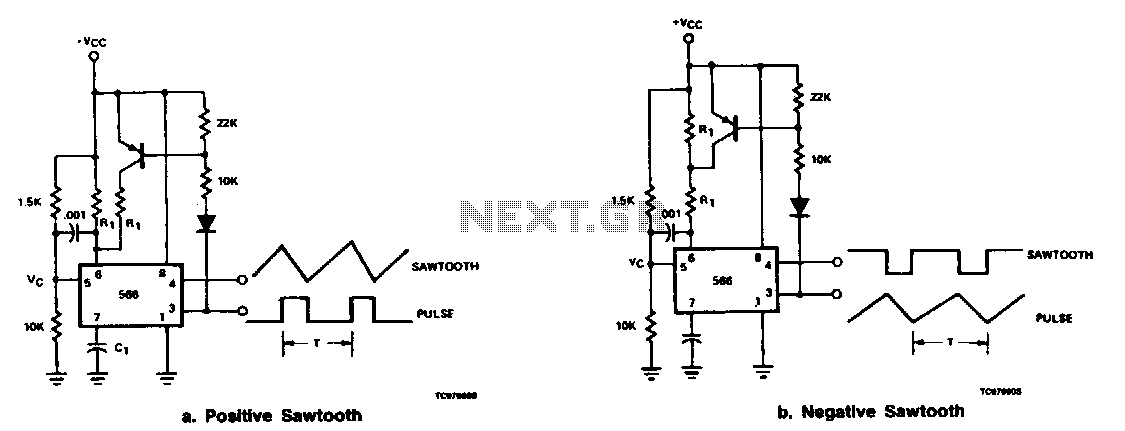
The output at pin 3 of the 566 can be utilized to deliver varying charge and discharge currents for capacitor Cl, resulting in a sawtooth waveform available at pin 4 and a pulse output at pin 3. It is...

This is a portable oscilloscope adapter that can be held in a breast pocket. Its operation is only sampling and sending to the host PC. Most of the functions of the oscilloscope are processed by the host PC. Therefore,...

This circuit is designed as a pocket-sized, high-performance audio oscillator. It can operate using a battery-powered version, which is feasible at a very low cost by utilizing a single quad op-amp to provide the entire active circuitry. The design...

In typical push-pull driver applications, the NPN-PNP transistor pair is alternately activated and deactivated using a square-wave signal. A basic driver circuit employs an inverter between the V1 and V2 inputs to toggle the output transistors. However, mismatched turn-on...
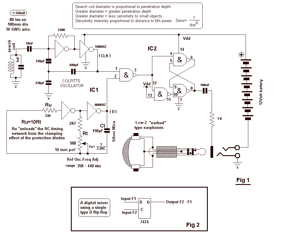
The circuit uses two CMOS ICs. IC1 uses inverters connected as a Colpitts oscillator of 100KHz; the LC frequency determining elements being the search coil and parallel resonating capacitor. An 80 turn close wound 30swg 100mm diameter coil will...
When the output is high, R3 and R4 are in parallel, and C1 charges through R1 until the current in R2 equals that at the non-inverting terminal. This action occurs when C1's voltage rises to 2/3 of the supply...