
Mini IR Theremin Circuit

The IR Theremin circuit is designed around the PIC18F452 microcontroller, which serves as the central processing unit for controlling the operation of the infrared sensor and generating audio output. The 2Y0A21/GP2D120 infrared sensor is employed for detecting the proximity of an object, which modulates the pitch of the sound produced by the speaker based on the distance of the object from the sensor. This interaction allows for an intuitive user experience, where moving closer or farther away from the sensor alters the pitch of the sound.
The power supply arrangement using four AA batteries is efficient for this application, providing sufficient voltage while maintaining portability. The absence of a voltage regulator simplifies the circuit design, as the battery voltage falls within the acceptable range for both the microcontroller and the IR sensor. It is essential to ensure that the batteries are fresh and capable of delivering the required voltage to maintain consistent performance.
The IR sensor's connections to the microcontroller are straightforward. The Power and Ground pins are connected to the appropriate voltage and ground references, while the Output pin is routed to pin RA0 of the PIC. The microcontroller's analog-to-digital converter (ADC) is configured to read the output voltage from the IR sensor, which varies with the distance of an object in proximity to the sensor. This ADC reading is then processed in the firmware to determine the corresponding pitch for the sound output.
The speaker connection is equally simple, with one side grounded and the other side connected to pin RD0 of the PIC. The microcontroller firmware is programmed to toggle this pin at varying frequencies, producing sound waves of different pitches based on the input received from the IR sensor. The resulting audio output is amplified by the speaker, creating an audible signal that corresponds to the distance measured by the infrared sensor.
Overall, the IR Theremin circuit exemplifies a minimalistic yet effective design that leverages the capabilities of the PIC18F452 microcontroller and the 2Y0A21/GP2D120 infrared sensor to create an interactive electronic instrument.The IR Theremin hardware schematic is deliciously simple in that the main input and output devices do not require many connections. This is usually a mixed blessing because less hardware, often means more software. The main devices used in the circuit are the 18F452, 2Y0A21/GP2D120 IR Sensor and the headphone speaker.
The power circuit here is just batteries. No voltage regulator was used because the batteries I have are all +1. 2v, so 4 AA Batteries x +1. 2v = +4. 8v which is within specification with the PIC and IR sensor. The IR Sensor only has three connections: Power, Ground and Output to the PIC`s pin 2 (RA0). This is set as an analog input for the A-to-D converter in the PIC. The connection to the speaker is one side going directly to ground and the other side of the speaker connecting to the PIC`s pin 19 (RD0). The firmware will tell this pin to alternate between on and off at certain frequencies to create the proper pitch output to the speaker.
🔗 External reference
Related Circuits

Below are three examples of controlling a relay from the PC's parallel printer port (LPT1 or LPT2). Figure A shows a solid-state relay controlled by one of the parallel port data lines (D0-D7) using a 300-ohm resistor and a...

A band-pass filter is presented as a single-channel circuit diagram in this article, specifically for audio applications. The filter has a high cutoff frequency (fH) of 50 Hz and a low cutoff frequency (fL) of 13 kHz, as illustrated...
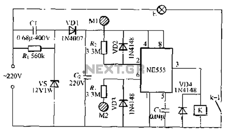
A use NF double touch lamp circuit based on a 55 base design, utilizing switches. It operates with 220V AC and includes a simple composition of a power-saving buck converter in conjunction with a half-bridge circuit. The circuit is...
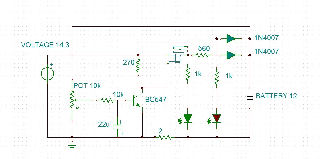
Using a transistor will not yield accurate results, and the adjustment process can become quite tedious. The circuit is technically correct; if the tripping point can be adjusted properly, it may function as intended. Vinod states that he created...
The receiver is based on a basic SA612 circuit. The local oscillator (LO) for the 20-meter band operates at approximately 9 MHz, with an intermediate frequency (IF) of 5.068 MHz. The IF filter employs two crystals and has a...
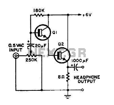
This is a simple headphone amplifier. Any NPN transistor can be used. The circuit can be powered by a 9V battery. The headphone amplifier circuit serves to boost audio signals to a level suitable for driving headphones. It typically consists...