
Headphone Amplifier circuit

The headphone amplifier circuit serves to boost audio signals to a level suitable for driving headphones. It typically consists of an NPN transistor, which functions as the main amplification component. The choice of the NPN transistor is flexible, allowing for various models based on availability and desired specifications.
The circuit operates with a 9V battery, providing sufficient voltage to ensure optimal performance. The input audio signal can be fed into the base of the transistor, where it is amplified. The collector of the transistor is connected to the power supply, while the emitter connects to the output, which leads to the headphones.
To optimize performance, it is advisable to include a biasing resistor at the base to set the operating point of the transistor. Additionally, coupling capacitors can be used at the input and output to block any DC offset, ensuring that only the AC audio signal is passed through to the headphones.
The output impedance should be matched appropriately to the headphones being used to maximize sound quality and prevent distortion. Overall, this simple headphone amplifier circuit is an effective solution for enhancing audio signals and can be easily constructed with basic electronic components.This is a simple headphone amplifier. You can use any NPN transistor. You can drive this circuit with a 9V batery.
Related Circuits
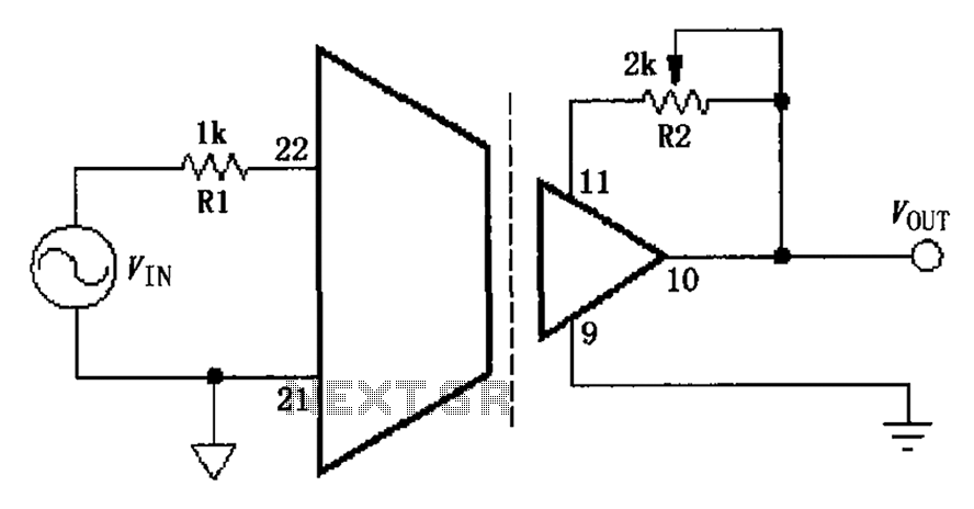
The gain adjustment circuit for the ISO103 is illustrated. The circuit features a gain trimming potentiometer, R2, which serves to enhance the gain accuracy and offset of the ISO103, thereby allowing for external adjustments. R2 provides a gain trim...
Figure 1 shows the circuit. A major change from all of the designs from that era is the speaker coupling capacitor - 1000uF (for a -3dB of 20Hz and a 8 Ohm load) was the most common value. This is...
This remarkably straightforward circuit enables the operation of one or two robust 12V 21W car bulbs in a flashing mode using a power MOSFET. Such devices are especially suitable for road, traffic, and yard alerts, as well as in...
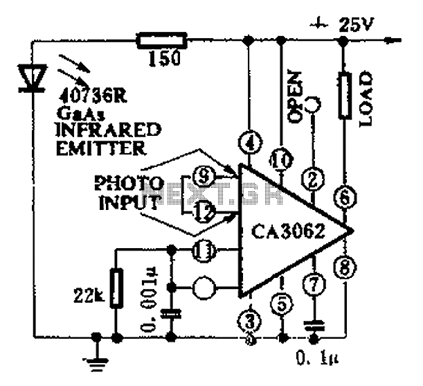
CA3062 is a combined photodetector and power amplifier that responds to the optical signal generated by the on/off output. The integrated circuit's transistor output saturation should be either on or off to prevent temperature rise in the silicon. When...
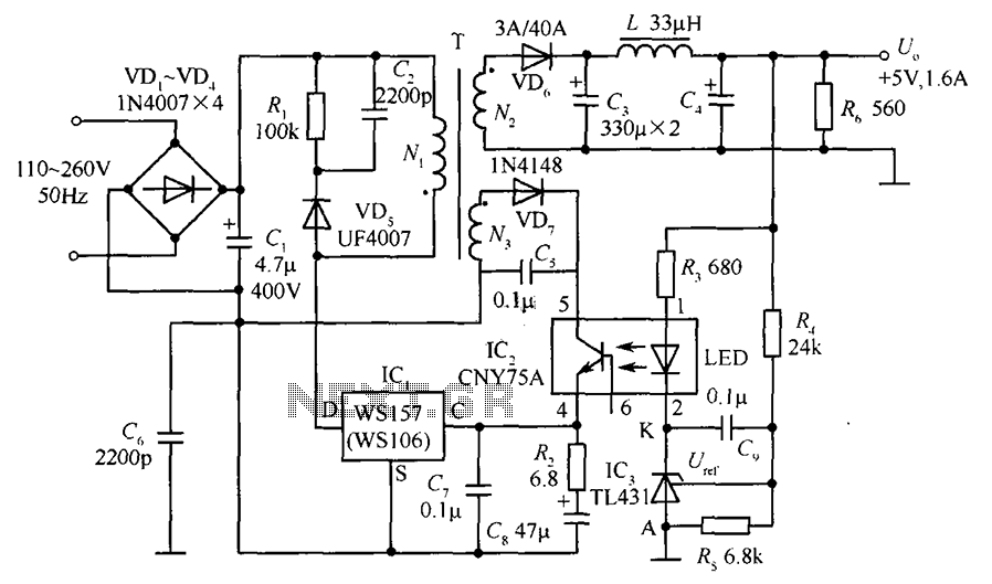
The circuit incorporates an optical coupler (CNY75A) and an adjustable precision shunt regulator (TL431). It includes current limiting resistors R3, R4, and R5 for the sampling resistor. As the output voltage (Uo) varies, the voltage across the sampling resistor...
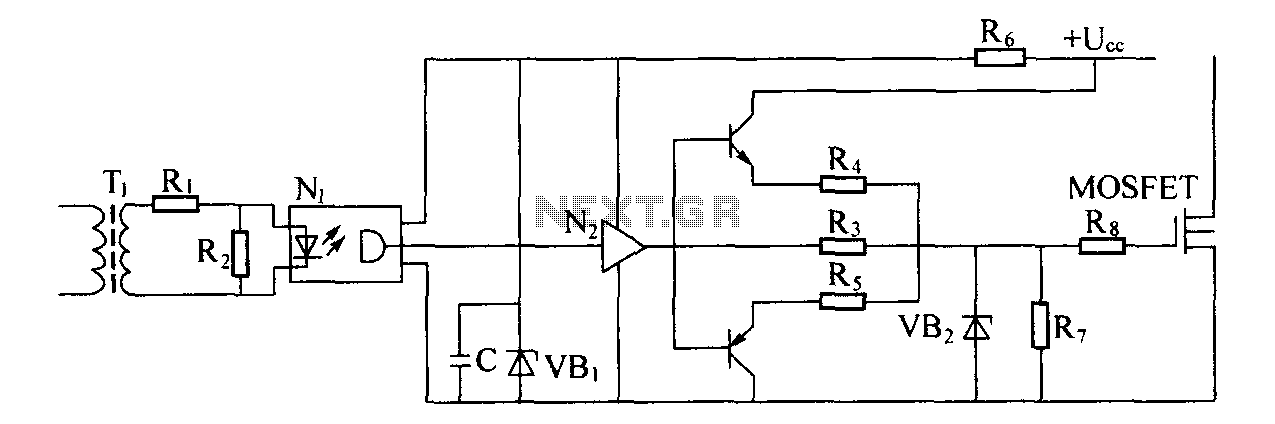
Driver circuit diagram: The primary function of the driver circuit is to serve as a variable width pulse width modulator output power amplifier, providing a drive signal to high voltage power switching devices. The driving circuit typically plays a...