
MINI ROULETTE

The described circuit operates as a compact and engaging roulette simulation, ideal for educational purposes or entertainment. The 4017 decade counter is a versatile component that counts pulses from the clock signal generated by the 555 timer. This configuration allows for the sequential illumination of each LED, creating a visually appealing effect that mimics the spinning of a roulette wheel.
The 555 timer, functioning in astable mode, continuously generates a square wave signal. The frequency of this signal is determined by the values of the timing capacitor (C2) and resistor (R3). The design choice of C2 directly impacts the speed of the LED cycling; larger capacitance will result in a slower cycle, while smaller capacitance will increase the speed. Resistor R3 plays a crucial role in ensuring that the circuit remains stable during operation, particularly when the SPIN button is activated and the LEDs are in motion.
The common limiting resistor R4 is essential for protecting the LEDs from excessive current, ensuring their longevity and consistent brightness. The arrangement of the LEDs in alternating colors not only enhances the aesthetic appeal but also helps in distinguishing the active LED during gameplay.
The inclusion of the piezo disk transducer (X1) adds an auditory element to the circuit, further enriching the user experience. This component converts the electrical oscillations from the 555 timer into sound waves, providing feedback that complements the visual display.
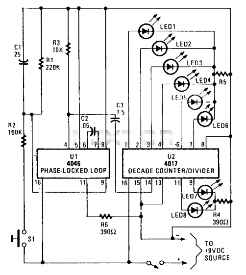
Overall, this mini battery-powered roulette circuit is a well-rounded project that combines principles of digital electronics, timing circuits, and sound generation, making it an excellent demonstration of basic electronic concepts.A circuit diagram for a mini battery-powered version of roulette is shown, This circuit uses a 4017 decade counter (IC2) driving 10 LEDs. Because only one LED is ever illuminated at any one time, a common limiting resistor R4 is used. They can also be placed in alternating red/green order for added effect. The counter IC2 is clocked by IC1, a clas sic 555 timer connected as an astable. When the SPIN button is pressed and then released, full speed is achieved, and then the display gradually slows down until it stops on a single number. Capacitor C2 governs the oscillator speed, and resistor R3 prevents instability when the LED rotation stops.
The piezo disk transducer, X1, is placed on the output of the oscillator to provide a sound effect. 🔗 External reference
Related Circuits
A strobe light generates a brief, intense pulse of electric current through a gas, resulting in a brilliant burst of light. The gas is typically one of two inert gases, xenon or krypton, which emit relatively white light when...
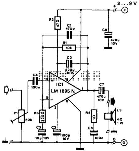
This amplifier operates with supply voltages ranging from 3 V to 9 V and can deliver an output power ranging from 100 mW to 1 W into a 4-ohm load. The bandwidth is approximately 20 kHz at a 3...
The circuit utilizes a 4046 Phase-Locked Loop (PLL) that incorporates a voltage-controlled oscillator (VCO), two phase comparators, a source follower, and a Zener diode to generate a low-frequency pulsed output of approximately 40 Hz. The frequency range of the...
This project is designed to prevent unauthorized access to personal belongings left on a beach towel while swimming, and it can also be utilized in office or workshop settings. The circuit is compact and can be powered by simple...
A simple function generator that produces a specific frequency. While awaiting the arrival of the AD9832 chip, a basic version of a Direct Digital Synthesis (DDS) synthesizer was developed using only the AT2313 microcontroller and a resistor network. This...
This miniature transmitter is easy to construct and its transmissions can be picked up on any standard FM receiver. It has a range of up to 1/4 of a mile or more. It is great for room monitoring, baby...