
Oscilloscope-Triggered Sweep using 555 IC

The application of the 555 timer in an oscilloscope circuit provides a cost-effective solution for generating a triggered sweep. The 555 timer operates in either monostable or astable mode, allowing it to produce precise timing intervals or continuous waveforms, respectively. In this configuration, the input operational amplifier serves as the signal detection mechanism, monitoring the incoming signal and providing the necessary trigger to the 555 timer.
When the input op-amp detects a threshold voltage, it sends a trigger pulse to the 555 timer. In monostable mode, this pulse initiates a single output pulse of a predetermined duration, which can be adjusted by changing the resistor and capacitor values connected to the timer. This output pulse can then be used to drive the horizontal deflection system of the oscilloscope, allowing for a synchronized display of the incoming signal.
In astable mode, the 555 timer continuously oscillates, generating a square wave output that can be used for repetitive sweep signals. This mode is particularly useful for applications requiring a stable and continuous display of waveforms. The frequency of the oscillation can be adjusted by selecting appropriate resistor and capacitor values, allowing for flexibility in the oscilloscope's sweep speed.
The integration of the 555 timer into an oscilloscope circuit not only enhances functionality but also significantly reduces the overall cost compared to more complex timing circuits. This makes it an ideal choice for budget-conscious designs without compromising performance. Proper consideration of the component values and circuit layout is essential to ensure optimal operation and reliability of the oscilloscope.We can use the 555 timer to hold the cost down of adding a triggered sweep to an economy oscilloscope. The timer is triggered by the circuit`s input op amp,.. 🔗 External reference
Related Circuits
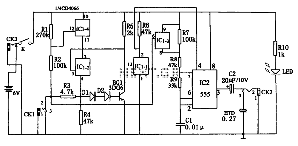
The circuit, illustrated in Figure five, employs a tri-state logic pen audio circuit. It primarily consists of a multivibrator, a four-way switch (CD4066, IC1), and several RC components. The multivibrator (555, IC2), along with resistors R7, R8, R9 and...
The reason why I am using an LCD display is because it allows me to display many characters and it doesn't need to be refreshed as 7-segment LED displays. Also, the interface requires less I/O pins. For this project,...
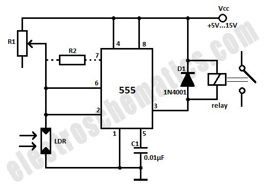
This light-activated relay circuit utilizes the 555 timer integrated circuit (IC) and a light-dependent resistor (LDR) to create a light-sensitive relay suitable for applications such as intruder alarm systems or automatic lamp control at sunset and sunrise. The potentiometer...
The following circuit illustrates a timer circuit with independent mark and space periods. It is based on the 7555 integrated circuit (IC). The high output duration is calculated by T(on) = 0.7 Ra Ct, while the low output duration...
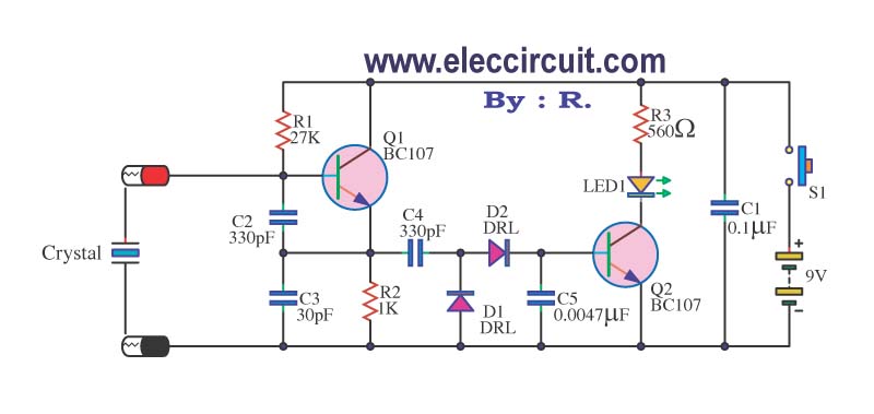
A multimeter cannot be used to test a crystal oscillator. Instead, a dedicated circuit is required, capable of checking crystals within the frequency range of 100 kHz to 900 MHz. This circuit is easy to construct and cost-effective. To construct...
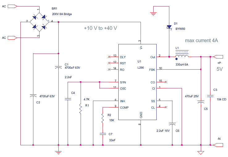
This circuit is based on the application note for the L296, a Power Switching Regulator from ST. The primary benefit of utilizing a switching regulator is the minimal heat dissipation observed in this design. In contrast, implementing a series...