
Mini Metronome
The described metronome scale involves a series of incremental tempo markings that are crucial for musicians to understand the pacing of their performance. This scale ranges from a slow tempo of 40 beats per minute (BPM) to a brisk tempo of 208 BPM, providing a comprehensive spectrum for practice and performance.
In an electronic metronome circuit, the implementation of such a scale involves several key components. The heart of the metronome is typically a microcontroller, which can be programmed to generate precise timing pulses at the specified BPM. The microcontroller interfaces with a timing circuit that may include a crystal oscillator to ensure accuracy.
The output from the microcontroller can drive a speaker or piezo buzzer, producing audible clicks or beeps at each metronome step. An LED may also be included to provide a visual cue that synchronizes with the audible output. The user interface may consist of buttons or a rotary encoder to allow the musician to select the desired BPM from the defined scale.
The circuit may also feature a display, such as a seven-segment or LCD screen, to show the current BPM selection. Power management components, including voltage regulators and capacitors, are essential to ensure stable operation of the circuit.
In summary, the electronic metronome circuit designed to accommodate the specified BPM scale would integrate a microcontroller, timing elements, audio output components, user interface controls, and power management features to deliver a reliable and user-friendly metronome for musicians.Finally mark the entire scale with the usual metronome steps as following: 40 - 42 - 44 - 46 - 48 - 50 - 52 - 54 - 58 - 60 - 63 - 66 - 69 - 72 - 76 - 80 - 84 - 88 - 92 - 96 - 100 - 104 - 108 - 112 - 116 - 120 - 126 - 132 - 138 - 144 - 152 - 160 - 168 - 176 - 184 - 192 - 200 - 208. 🔗 External reference
Related Circuits
A small audio test generator is highly effective for quickly tracing signals through audio equipment. Its primary function emphasizes speed over precision. Typically, a single sine-wave signal of approximately 1 kHz suffices, and distortion levels are not critically important....
This mini audio amplifier will test the audio stages in amplifiers such as the front end of FM bugs. You can also use it on lots of our other projects as well as the output stages of radios. It...
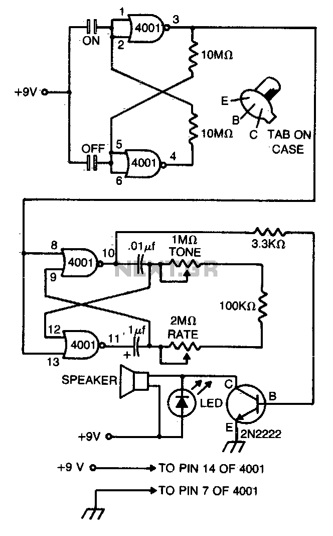
This compact metronome operates for years on a single nine-volt transistor battery. It features both tone and pulse rate controls and utilizes touch plates for starting and stopping. The device can be housed in a case no larger than...
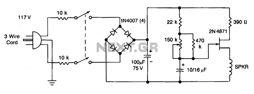
The frequency of the UJT oscillator is determined by the 100 µF capacitor and the effective resistance of the 22 Ω and 470 Ω resistors, along with a potentiometer. The rate can be varied from 42 to 208 beats...
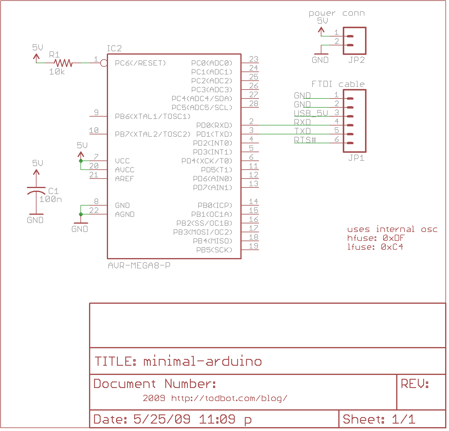
The minimal Arduino circuit is straightforward. It utilizes an internal 8MHz oscillator, similar to the Lilypad Arduino, but does not include a USB-to-serial interface. This functionality must be provided using an FTDI USB-to-serial cable or an older Arduino board....
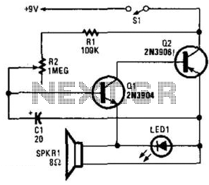
Two complementary transistors create a basic oscillator with a frequency range of approximately 0.5 to several Hz. This circuit serves as a metronome, timer, or pacer for exercise equipment. The oscillator circuit utilizes a pair of complementary transistors, typically one...
Warning: include(partials/cookie-banner.php): Failed to open stream: Permission denied in /var/www/html/nextgr/view-circuit.php on line 713
Warning: include(): Failed opening 'partials/cookie-banner.php' for inclusion (include_path='.:/usr/share/php') in /var/www/html/nextgr/view-circuit.php on line 713