
minimal arduino with atmega8

The minimal Arduino circuit design is based on the ATmega8 microcontroller, which operates at a frequency of 8MHz using its internal oscillator. This configuration eliminates the need for an external crystal oscillator, simplifying the circuit design and reducing component count. The absence of a built-in USB-to-serial interface necessitates the use of an FTDI USB-to-serial cable or an older Arduino board to facilitate programming and serial communication.
To program the ATmega8, a modified bootloader is essential. The bootloader allows the microcontroller to receive firmware updates through the serial interface. The bootloader's functionality is critical, as it enables the chip to be reprogrammed without requiring an external programmer for every update. The variant of the bootloader used in this setup is based on the Arduino NG bootloader, which has been tailored to suit the ATmega8 architecture.
Programming the bootloader onto the ATmega8 can be performed using an AVRISPmkII programmer connected through the ICSP header. This method is efficient and reliable. The process involves loading the ATmegaBOOT.hex file, which contains the bootloader code, onto the microcontroller. For users who prefer graphical interfaces, the Arduino Integrated Development Environment (IDE) can be configured to recognize the new board type, allowing for straightforward programming through the IDE.
The board configuration requires specific entries in the boards.txt file, detailing parameters such as upload protocol, maximum upload size, and fuse settings. These entries ensure that the Arduino IDE communicates effectively with the ATmega8 microcontroller, allowing for proper sketch uploads and board management.
Once the bootloader is successfully installed, the circuit can be tested either while connected to the Arduino board or on a separate breadboard designed for minimal setups. This flexibility allows for experimentation and development in various environments, making it an excellent choice for prototyping and educational purposes.
The minimal Arduino approach is a testament to the versatility of the Arduino platform, showcasing how simple modifications can lead to effective and functional designs for various applications.The minimal Arduino circuit is dead simple. It relies on the internal 8MHz oscillator (like the Lilypad Arduino). And like the Lilypad, it doesn`t include a USB-to-serial. You have to provide that with a FTDI USB-to-serial cable or with an old Arduino board. While the circuit is very similar to a Lilypad Arduino, the chip used is different. The ATmega8 has less memory and must be programmed slightly differently than the Lilypad`s ATmega168. So a modified Arduino bootloader needs to be programmed into the ATmega8. The bootloader is a small program on the chip that listens to the serial port on power up and can reprogram the rest of the chip if instructed to. Here, a variant of the standard Arduino NG bootloader is used. The modifications are: Unzip this file into the arduino-0015/hardware/bootloaders directory of your Arduino installation to create the directory atmega8_noxtal .
The zip file contains: Actually programming the bootloader to the ATmega8 chip can be done in a few ways. I prefer using an AVRISPmkII programmer and an old Arduino board. Seat the ATmega8 into the Arduino, plug the AVRISP into the 6-pin ICSP header, plug both into USB, and program the ATmegaBOOT.
hex file. If you are familiar with the command-line, go into the atmega8_noxtal directory and type make isp to program. If not, you can have the Arduino software program it for you once you tell it about this new kind of Arduino board.
Because this minimal Arduino setup isn`t exactly like any other previous Arduino boards, we need to tell the Arduino software how to talk to it. In the Arduino directory, there is a file called arduino-0015/hardware/boards. txt that does this. Open that file in a text editor and add these lines to it: ############################################################## atmega8noxtal.
name=ATmega8-noxtal @8MHz atmega8noxtal. upload. protocol=stk500 atmega8noxtal. upload. maximum_size=7168 atmega8noxtal. upload. speed=38400 atmega8noxtal. bootloader. low_fuses=0xe4 atmega8noxtal. bootloader. high_fuses=0xc4 atmega8noxtal. bootloader. path=atmega8_noxtal atmega8noxtal. bootloader. file=ATmegaBOOT. hex atmega8noxtal. bootloader. unlock_bits=0x3F atmega8noxtal. bootloader. lock_bits=0x0F atmega8noxtal. build. mcu=atmega8 atmega8noxtal. build. f_cpu=8000000L atmega8noxtal. build. core=arduino The next time you start up the Arduino software, you should have a new entry of ATmega8-noxtal @8MHz in the Boards menu. It will look something like this: Once the bootloader has been installed, you can leave it plugged into the Arduino board to test it out, or you can remove it and place it on your minimal Arduino breadboard.
To upload sketches to it, the easiest way I`ve found is to run a few wires from an old Arduino board to the breadboard: This minimal Arduino idea is nothing new. Many others have done similar things. If I could have found an Arduino clone that used an internal 8MHz oscillator on ATmega8, I would`ve used it instead.
Some of the pages I referenced: 🔗 External reference
Related Circuits

Sip-and-Puff (SNP) controllers are widely recognized devices, often utilized in electric wheelchairs, enabling individuals with limited hand mobility to control their wheelchairs or other devices through inhaling (sipping) or exhaling (puffing) into a straw. The intensity of the inhalation...
Part fill valves are commonly utilized in rainwater tanks. The valve activates when the water level in the tank drops to a low position. Part fill valves play a crucial role in the management of water levels in rainwater harvesting...
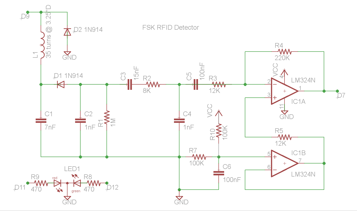
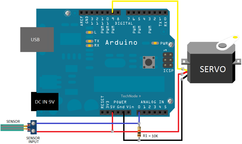
This document describes the construction of an RFID reader utilizing an Arduino (specifically tested with the Nano 3.0, although other models may also be compatible), a hand-wound wire coil, and various low-cost common components. RFID readers are devices manufactured...
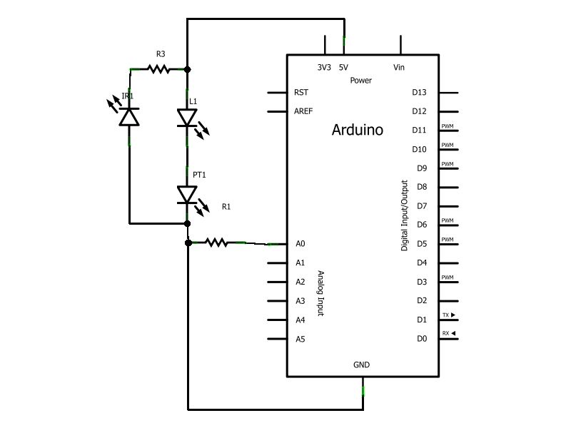
Have you ever wanted to create a line-following robot but found infrared sensors too expensive? If you are located in the UK and have access to a Maplin store nearby, you can purchase infrared transmitters and receivers for just...
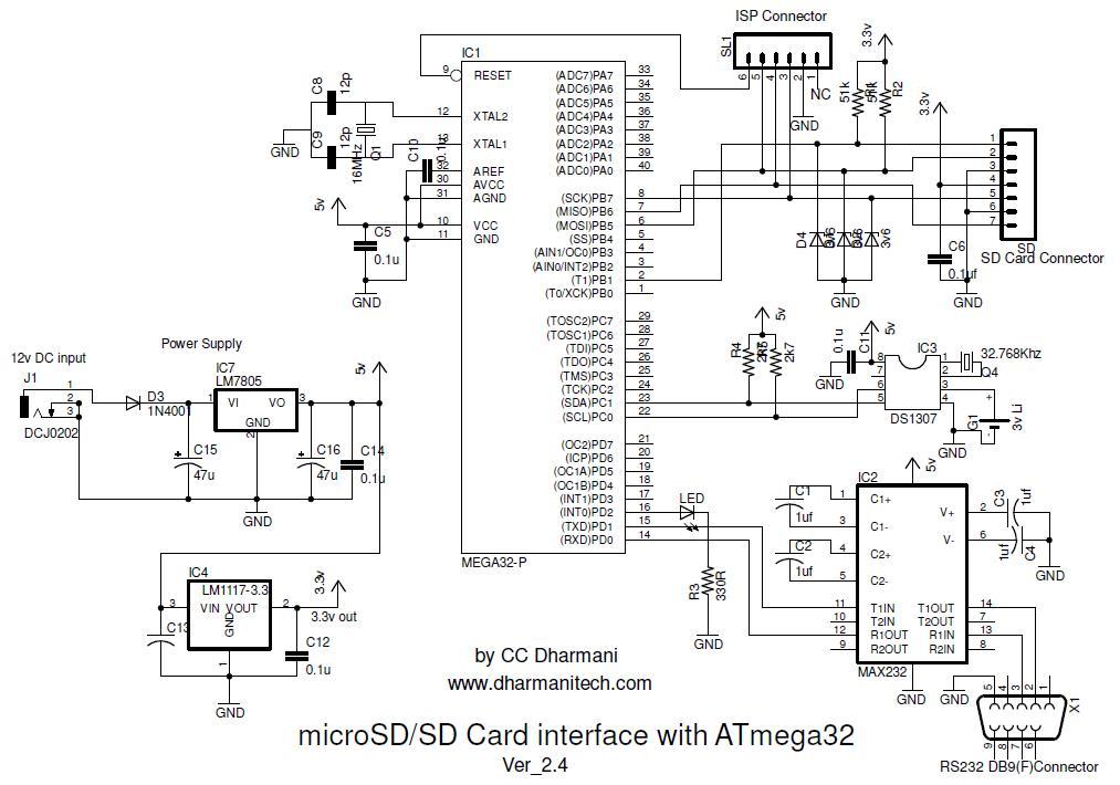
This project focuses on interfacing a microSD card, which is an affordable option for adding substantial memory to embedded systems. The microSD card is compatible with the SPI bus, simplifying the interfacing process. SD card adapters are readily available,...
This section of code outlines the main sequence of operation for the sequencer. A for loop is utilized to determine which step the sequencer is operating in. Within this loop, an address is generated using the assignByteToPins() function, which...