
Unijunction metronome

The UJT (Unijunction Transistor) oscillator circuit operates by utilizing the unique characteristics of the UJT to generate a repetitive waveform. The frequency of oscillation is primarily influenced by the timing capacitor (100 µF) and the resistive components, which include a fixed 22 Ω resistor, a fixed 470 Ω resistor, and an adjustable potentiometer. The combination of these resistive elements creates a voltage divider that controls the charging and discharging cycle of the capacitor, thus determining the oscillation frequency.
The UJT oscillator can achieve a frequency range from 42 to 208 beats per minute, making it suitable for various applications such as timing circuits, tone generation, or as a pulse generator in other electronic systems. The UJT's ability to switch on and off rapidly allows for precise control over the output waveform, which can be a square wave or sawtooth depending on the configuration of the circuit.
For safety considerations, it is essential to house the entire circuit within an insulated enclosure. This not only protects the components from environmental factors but also minimizes the risk of electrical shock. Alternatively, using a grounded three-wire cord ensures that any fault currents are safely directed to the ground, providing an additional layer of safety for the user.
Overall, the UJT oscillator circuit is a versatile and effective solution for generating variable frequency signals, with important design considerations for safety and reliability.The UJT-oscillator frequency is determined by the 100 µ¥ capacitor and the effective resistance of the 22 and 470 resistors and the potentiometer. Rate can be varied from 42 to 208 beats/minute. The circuit should be housed in an insulated box for safety, or use ground (3-wire cord).
Related Circuits
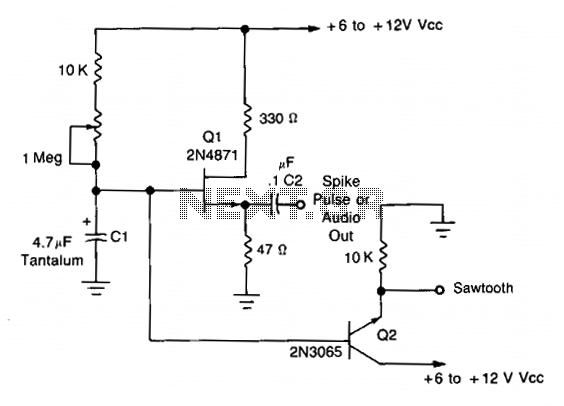
This simple oscillator utilizes a 2N4871 UJT to generate pulses ranging from 0.2 to approximately 20 Hz. A spike can be observed at C2, while a sawtooth waveform is present at the emitter of Q2, measuring about 2-3 V...
The figure illustrates a simple project schematic of a metronome. A metronome is a device utilized by musicians to produce continuous beats through a speaker. The metronome circuit typically consists of several key components that work together to generate a...
This is a metronome circuit that produces a mechanical sound characteristic. A metronome with a mechanical sound character enhances the enjoyment of musical practice and performance. The metronome circuit is designed to generate a rhythmic sound that aids musicians in...
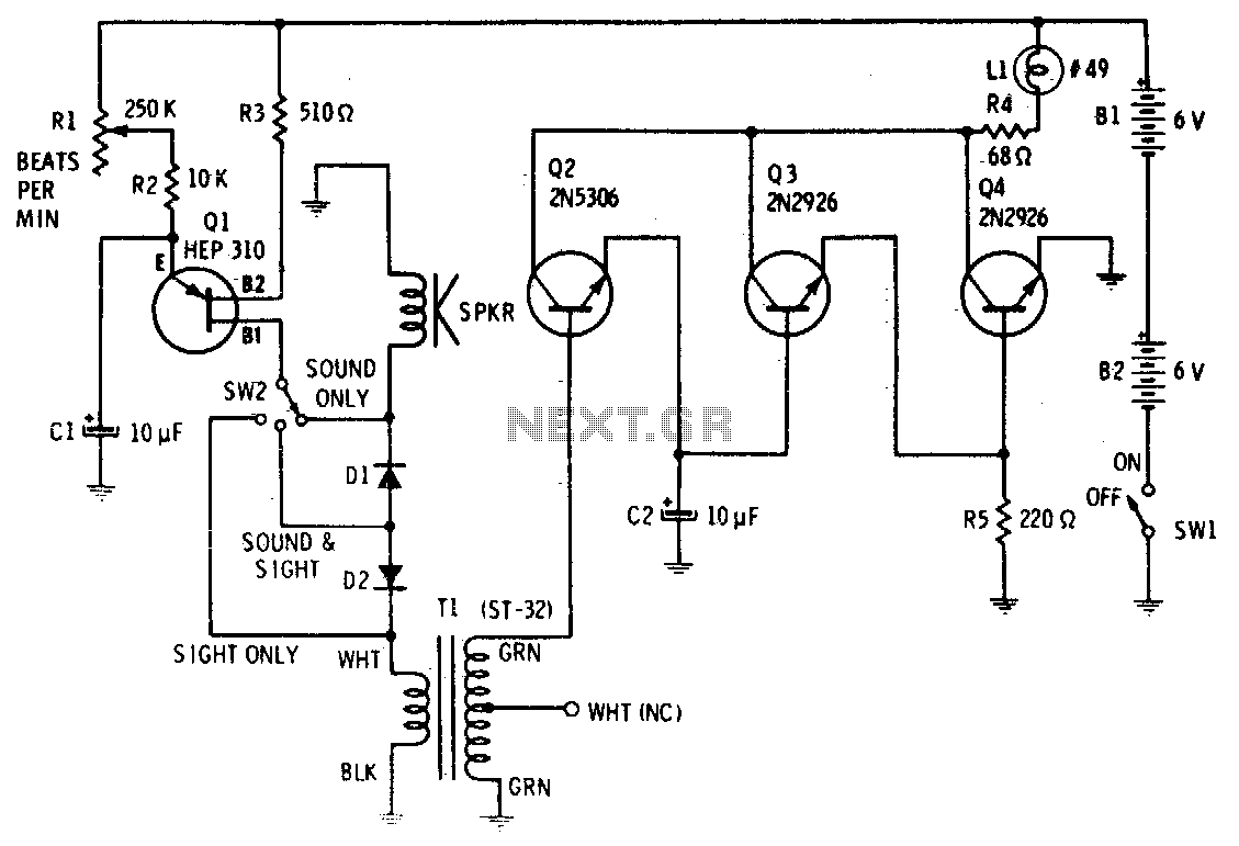
Precise, adjustable control of beats per minute ranges from a slow tempo of 18 to a rapid tempo of 500. These beats are generated acoustically through a speaker, accompanied by a light that flashes in synchronization. When switch SW1...

Q1 & Q2 provide linear frequency operation of IC1 following P1 resistance variation. Q3 was added in order to obtain a louder click, similar to clockwork metronomes. A 12V micro battery was used to obtain a higher output power...
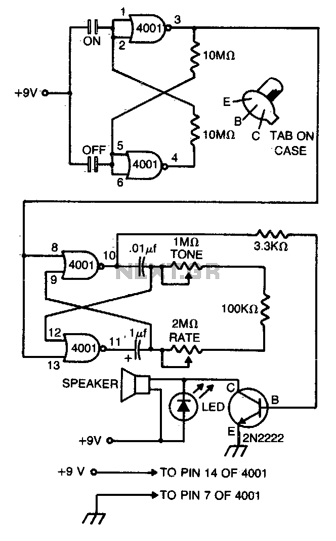
This compact metronome operates for years on a single nine-volt transistor battery. It features both tone and pulse rate controls and utilizes touch plates for starting and stopping. The device can be housed in a case no larger than...