
Mini strobe light

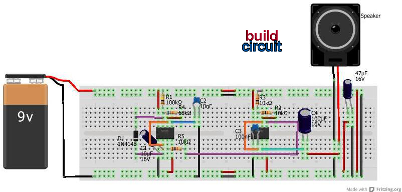
The circuit utilizes the NE555 timer IC configured in astable mode, functioning as a self-oscillator to generate a square wave output. The frequency of oscillation is determined by the values of the timing resistor and capacitor connected to the NE555. A variable resistor (VR) is included in the circuit to allow for the adjustment of the pulse width, thereby changing the frequency of the output signal. The output frequency can range from 40 Hz to 166 Hz, depending on the resistance value set on the variable resistor.
An LED is connected to the output of the NE555, which causes it to blink in synchronization with the oscillating frequency, creating a strobe light effect. This strobe light can be used in various applications, including visual demonstrations of sound waves and vibrations. The circuit also includes a speaker, which is driven by a 3V AC power transformer. The speaker cone vibrates at a frequency of 50 Hz, and by adjusting the variable resistor, the oscillation can be fine-tuned to 51 Hz. This allows for the observation of the speaker cone's slow vibrations at a 1 Hz rate when viewed under strobe lighting conditions.
In educational settings, this circuit serves as an effective tool for teaching concepts of sound, vibration, phase, and frequency. It can also be employed in practical applications to evaluate the mechanical stability of components on a printed circuit board (PCB). The simplicity and low cost of the design make it accessible for various learning and experimental purposes.This is a mini strobe light. NE555 is used as a self oscillator. The width of output pulse is changed by the variable resister. 25msec means 40Hz. 6m sec means 166Hz. A LED is connected on the output of this oscillator. Therefore LED twinkles from 40Hz to 166Hz. I lighted a speaker by this twinkle LED. The cone of a speaker is vibrated by 50Hz with 3V-AC power transformer. I adjusted the VR to oscillate 51Hz. Then, I can watch the corn of the speaker vibrates slowly with 1Hz. A strobe scope is used in order to research the vibration. This is very cheap one. If you are the teacher, you can teach the children that the sound is a vibration of the air. Also you can teach that the concept of phase and frequency with this equipment with this machine. If you are the young man, you can have a time with your girl friend in the dark room.( Last month I looked this light with 5 gentlemen. It was not enjoyable time HIHI) Description add on 10 Dec 2000: I forget to say about most important thing.
Such a instrument can be uaed to evaluate the mechanical stability of the parts on the print boad. 🔗 External reference
Related Circuits
This project involves a simple light-activated police siren utilizing a light-dependent resistor (LDR) and an NE555 timer. It is advisable to complete some preliminary projects before attempting this one. The NE555 timer, configured in slow astable mode with a...
2000 Plymouth Breeze Dash Light Wiring Diagram. The 2000 Plymouth Breeze dash light wiring diagram provides a detailed overview of the electrical connections and components associated with the vehicle's dashboard lighting system. This diagram serves as a crucial reference for...
This is a Courtesy Light Extender for vehicles. It extends the ON time of the interior lights when a door is closed, allowing passengers to see where they are seated. The Courtesy Light Extender circuit is designed to enhance the...
This project describes a new economical solution of home light control systems. The presented home light control system can be used for different sophisticated home applications. The control system consists of a PC, and control circuitry and the electrical...

The circuit utilizes a 555 timer IC to create a lighting group delay effect, as illustrated in Figure 2-46. It consists of the 555 IC along with a resistor and capacitor configuration that establishes the delay. The circuit remains...
The inquiry pertains to the connection of lights that flash when a phone rings. This feature is particularly beneficial in noisy environments, such as workshops, where hearing the phone may be difficult. A device designed for this purpose is...