
PC home light control system

The home light control system integrates a personal computer (PC) with specialized control circuitry and connected electrical devices to form a comprehensive lighting management solution. The primary component, the PC, serves as the central processing unit, running intelligent control software developed in a high-level graphical programming language, specifically Visual Basic. This software is responsible for user interface design, allowing users to easily manage and control the lighting system.
The control circuitry interfaces with the PC and is designed to process commands received from the software. It typically comprises microcontrollers or microprocessor units that execute the logic for light control, including dimming, scheduling, and scene setting. The circuitry may include relay modules or solid-state switches to handle the high voltages and currents associated with home lighting systems.
In addition to the hardware components, the system may utilize various communication protocols, such as RS-232, USB, or even wireless technologies like Wi-Fi or Zigbee, to facilitate communication between the PC and control circuitry, as well as between the control system and the electrical devices. This allows for remote control and automation of lighting, enhancing user convenience and energy efficiency.
The overall design emphasizes flexibility, enabling the control system to be adapted for various sophisticated home applications, such as automated lighting in response to occupancy or time of day, integration with security systems, and compatibility with smart home devices. This comprehensive approach not only provides an economical solution for home lighting control but also enhances the functionality and user experience of residential environments.This project describes a new economical solution of home light control systems. The presented home light control system can be used for different sophisticated home applications. The control system consists of a PC, and control circuitry and the electrical devices. The intelligent control software, which has been developed using high level graphical programming language (Visual Basic). A complete solution of a home control system is presented in this project. The home lights was fully controlled by the PC and the co 🔗 External reference
Related Circuits
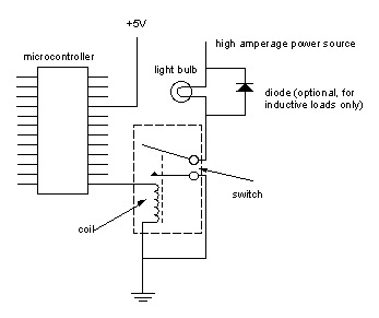
Digital output from a microcontroller is typically a low-amperage signal. For example, when a pin is set HIGH on the microcontroller (in Wiring/Arduino, it is digitalWrite(somePin, HIGH);), the voltage from that pin is usually +3.3V or +5V, with the...
This document details a dual-axis stepper motor controller design and printed circuit board for an equatorial mount. Acknowledgment is given to Bill Prewitt for his assistance in creating this webpage. An encapsulated PostScript file containing the artwork for both...
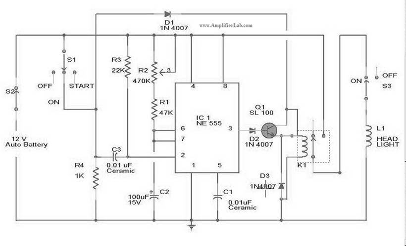
The circuit diagram for the automatic headlights turn-off circuit is presented here. This circuit can be installed in a car. The automatic headlights turn-off circuit is designed to enhance vehicle safety and convenience by ensuring that the headlights are automatically...
is circuit was requested from an email. It will allow your car headlights to flash on and off at the same time or it will cause them to flash alternately. The circuit is based on the 555 timer. It...
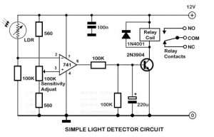
An ambient light sensor circuit is a circuit that utilizes light intensity to perform various applications. An ambient light sensor circuit typically consists of a light-dependent resistor (LDR) or phototransistor that detects the intensity of ambient light. The sensor converts...
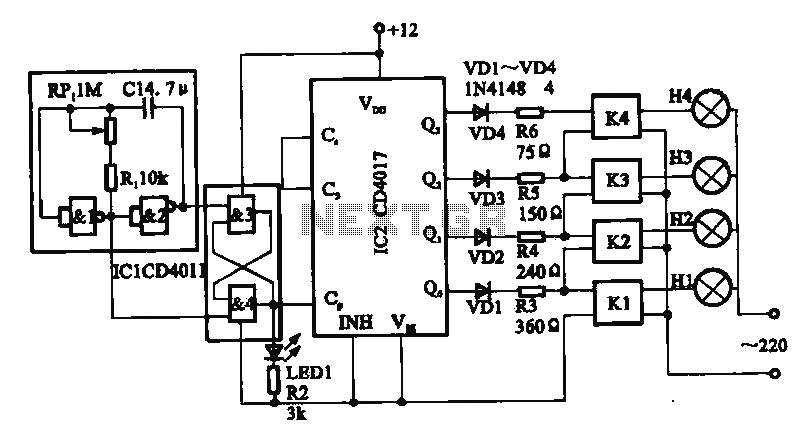
This circuit illustrates a circular lighting control system. It consists of four two-input NAND gates from the CD4011 series, which form a non-inverting multivibrator. This multivibrator generates a pulse that is used to shape the output of an RS...