
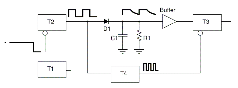
Police Siren Circuits with IC555 Schematic Diagram

The astable multivibrator configuration employed in this circuit is a fundamental application of the 555 timer IC, which operates in a continuous oscillation mode. In this setup, the timing components R1, R2, and C1 set the frequency of oscillation. The frequency can be calculated using the formula:
\[ f = \frac{1.44}{(R1 + 2R2) \cdot C1} \]
This relationship indicates that by adjusting the values of R1, R2, and C1, the output frequency can be fine-tuned to achieve the desired low-frequency square wave.
The output from IC1 at pin 3 is then fed into IC2, which acts as a frequency multiplier or modulator. The value of resistor R5 plays a crucial role in shaping the output signal from IC1, allowing it to be transformed effectively into a higher frequency range of 440 Hz to 550 Hz. This frequency range is characteristic of audio signals that can be produced by sound-generating devices.
Transistor Q1 is used as a switching device to amplify the output signal from IC2. The base of Q1 receives the modulated signal, allowing the transistor to drive a speaker or piezo buzzer, thus converting the electrical signal into sound. The design of this circuit ensures that the output sound mimics the tone and pattern of a police siren, which is typically designed to capture attention and alert individuals in the vicinity.
Overall, this circuit exemplifies the integration of basic electronic components to create a functional and effective sound-generating device, ideal for applications such as alarms and signaling systems. Proper selection of component values and configurations will ensure optimal performance and desired auditory output.The employment of the circuit IC1 which build survive astable multi vibrator circuit. self-control gesticulate frequency low origin comes exposed the way pin 3 take approximately 1 Hz by frequency charge with the intention of s were fixed by the value, R1, R2, C1 signal the frequency will have that to approach out pin 3 ways which built cause alo ng well with 5 of IC2 transform R5. By the frequency from IC1 pray contact compute up with the frequency by IC2 launch will valuable about 440 Hz - 550 Hz the frequency had with the intention of to sent arrive out pin 3 ways. Which remain take flatter up of IC2 the connection goes to grasp along well with B of Q1 in lieu of enlarge the trend comes to sing bail get to the sound of the circuit with the purpose of comes unacceptable resemble the sound of regulate distress signal.
You are reading the Circuits of Police Siren Circuits with IC555 And this circuit permalink url it is 🔗 External reference
Related Circuits
An individual is attempting to design an alarm using an LM555 timer but is unsure of where to begin. Friends who have experience in designing alarms are providing support. The LM555 timer is a versatile integrated circuit widely used in...
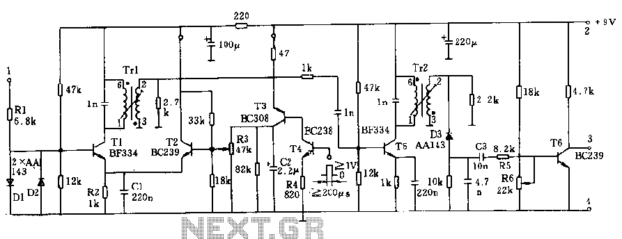
The two unspecified polarized capacitors (one directly above the transformer and one directly to the right of the transformer) are actually each a pair of 470 µF capacitors in parallel (for a total of four 470 µF capacitors). These...
The circuit operates at a voltage of 9V with a current consumption of only 5mA. It allows for frequency adjustment within the range of 150 to 180 kHz, featuring a bandwidth of approximately 20 kHz. This configuration ensures that...
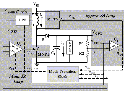
The main ΣΔ loop operates in steady state and is fully controlled by summing comparator Q2. This comparator amplifies the ripples of the sensed inductor current and output voltage with gains KI and KV, respectively, to generate an internal...
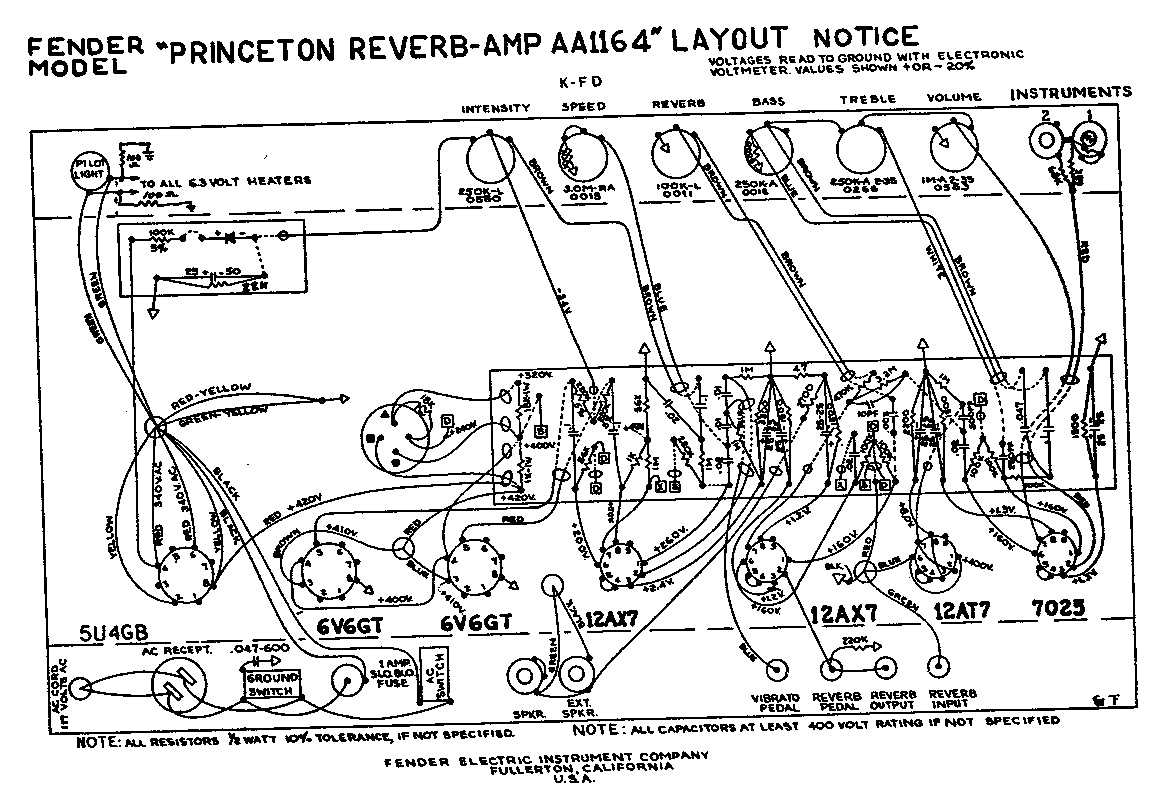
A 1969 Princeton Reverb amplifier is identified as utilizing the AA764 circuit design. Various online resources provide schematics for Fender amplifiers. The Princeton Reverb amplifier, particularly the model from 1969, is renowned for its warm tone and versatile sound characteristics,...
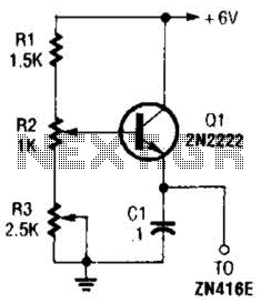
This regulator can be used with a +6-V source to supply the ZN416E low-voltage TRF radio receiver IC with the necessary +1.5 V. R3 sets the output voltage. The circuit utilizes a voltage regulator designed to convert a +6 V...