
Miniature Wideband Amplifier Circuit

The NE5205 wideband amplifier is designed for applications requiring high-frequency performance and stable gain. The fixed gain of 20 dB across a frequency range of up to 450 MHz makes it suitable for various RF applications, including signal amplification in communication systems. The internal design of the NE5205 allows for easy cascading, enabling multiple amplifiers to be connected in series to achieve higher overall gains without the need for complex external compensation circuits.
In the described configuration using two NE5205S amplifiers, the overall gain is effectively doubled to 40 dB, enhancing the system's capability to amplify weak signals received by the antenna. This cascading setup is particularly advantageous in scenarios where maintaining signal integrity is critical, such as in long-distance communication or in environments with significant signal attenuation.
The implementation of coupling and decoupling capacitors is essential in this circuit to ensure proper signal transmission while filtering out unwanted noise and preventing DC bias from affecting the performance of the amplifiers. These capacitors allow AC signals to pass while blocking DC components, thereby maintaining the integrity of the amplified signal.
Furthermore, the option to power the amplifier through the signal-carrying coaxial cable simplifies installation and reduces the need for additional power lines, making it feasible to deploy the amplifier directly at the antenna site. Utilizing a weatherproof enclosure ensures that the amplifier remains protected from environmental factors, thus enhancing its reliability and longevity in outdoor applications. This design consideration is critical for maintaining consistent performance in various weather conditions, making it an optimal choice for outdoor RF applications. Except for the coupling and decoupling capacitors, IC1 is a complete wideband amplifier that has a fixed gain of 20 dB to 450 MHz. No external compensation is required. since the NE5205 functions as a gain block, two or more cart be easily cascaded to provide additional amplification.
In this circuit, which uses two NE5205S, the overall gain is 40 dB. JF the power supply is fed through the signal-carrying coaxial cable, the amplifier can be mounted in a weatherproof enclosure directly at the antenna.
Related Circuits
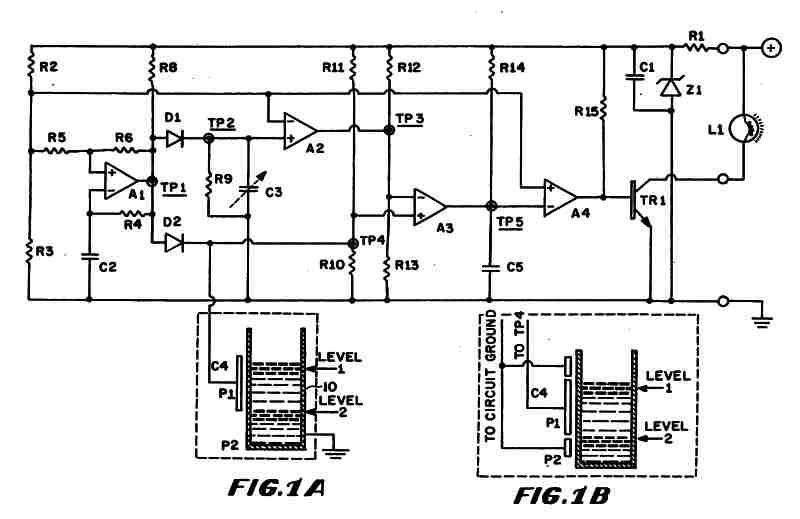
Figure 1 (A) depicts the circuit diagram of one embodiment of the fluid level detector designed. The circuit is typically powered by a 12-volt automobile battery, which is reduced to a 5-volt DC source using a voltage regulator consisting...
An infrared wired repeater circuit is designed to control appliances from a remote location. Parts List: R1: 1k Resistor (1), R2: 3.3k Resistor (1), R3: 10k Resistor (1). The infrared wired repeater circuit serves as an interface for controlling various...
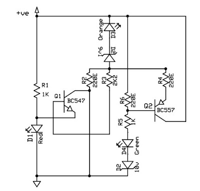
This circuit is a 12V battery checker that utilizes three LEDs to indicate different voltage levels. The red LED illuminates when the battery voltage is between 8V and 10V, the orange LED activates at voltages ranging from 10.5V to...
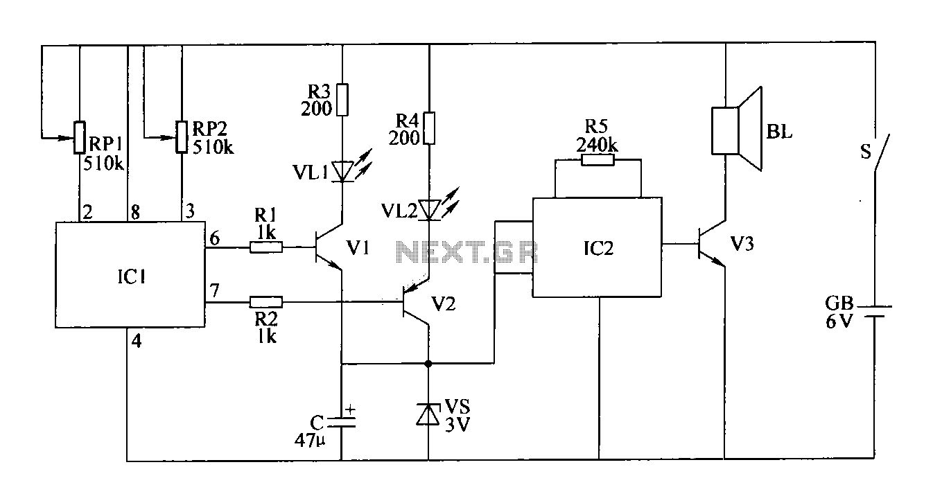
The double-limit temperature alarm circuit consists of a temperature detection control circuit, a temperature indicating circuit, and an alarm sound circuit. The components selected include resistors R1 to R5, which should be 1/4W metal film or carbon film resistors....
Arcing completes a circuit -- closes a system -- between two voltage potentials. When arcing occurs, two oppositely charged static voltage potentials can cancel each other out. The arcing problems that occur are usually between two electrically isolated voltage...

This document outlines the design process of a control circuit for a stepper motor. Given the characteristics of the stepper motor, the control circuit was developed as a state machine that transitions through four output states depending on two...