
DIY Infrared Sensor Module using Arduino
To start wiring the infrared LEDs, place a 220-ohm resistor in the same row as the cathode of the IR LED and connect it to ground, ensuring both LEDs are wired correctly. Next, connect the anodes of both IR LEDs to the power rail. Moving on to the phototransistors, the cathode of the red LEDs should be placed in the anode row of the phototransistors. Then, a 1k-ohm resistor should be positioned inside the cathode of the phototransistor.
The phototransistors need to be connected to analog inputs zero and one. Connect the cathode of the phototransistor (before the 1k-ohm resistor) to analog input zero on the left and analog input one on the right. After wiring in the power supply from the Arduino (+5V and Ground), waving a hand in front of the IR LED/phototransistor pairs should cause the red LEDs to fade from dim to bright and back again. If the LEDs respond correctly to hand movement, the basic prototype is complete. However, if there are no results from the hand movement, it is necessary to check the wiring, as the IR LEDs might be burned out or incorrectly positioned.
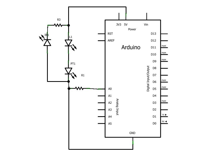
A detailed electronic schematic for the described line-following robot sensor module consists of the following components and connections:
1. **Infrared LED and Phototransistor Pair**: The circuit includes two pairs of infrared LEDs and phototransistors. Each infrared LED should be connected in series with a 220-ohm resistor to limit current and protect the LED from damage. The cathode of the infrared LED connects to ground, while the anode connects to the positive power rail (+5V).
2. **Phototransistor Configuration**: The phototransistor is connected such that its anode connects to the cathode of the corresponding infrared LED. The cathode of the phototransistor is then connected to a 1k-ohm resistor, which is further connected to the analog input pins of the Arduino (A0 and A1). This configuration allows the phototransistor to detect the reflected infrared light from obstacles, with the resulting voltage change being read by the Arduino.
3. **Analog Input Wiring**: The left phototransistor's cathode connects to analog input A0, while the right phototransistor's cathode connects to analog input A1. This setup enables the Arduino to differentiate between the signals received from each phototransistor, facilitating line-following capabilities based on light reflection.
4. **Power Supply**: The entire circuit is powered by the Arduino's +5V and ground connections. Proper power supply connections are essential for the circuit's functionality.
5. **Testing and Calibration**: After completing the wiring, testing the circuit involves waving a hand in front of the sensor pairs. The expected outcome is that the red LEDs will illuminate in response to the infrared light being reflected back from the hand. If the LEDs do not respond, troubleshooting steps should include verifying the orientation and functionality of the infrared LEDs and phototransistors, as well as checking all connections for correctness.
This schematic provides a foundational understanding for constructing a low-cost line-following robot utilizing infrared sensors, suitable for hobbyists and educational projects.Have you ever wanted to make a line following robot but the infrared sensors were too expensive for you Do you want to upgrade the robot in my other instructable Also, if you`re from the UK and have a maplin store near you, you`ll be able to get some IR transmitter and receivers for 99p (They`re side facing LED/phototransistors, so you can have a low-profile sensor module), More on this at the end of the instructable. You want to take your bread board and your infra red LED`s and photo transistors and place them side by side (1 hole apart) in the bread board, repeat for the other infra red pair. Now let`s start wiring up the infrared LED`s first, place a 220 Ohm resister in the same row as the IR LED cathode then wire it to ground, and make sure to wire both.
Next you need to wire up both of the IR LED anodes to the power rail. Now we`re moving onto the photo transistors. Take the red LED`s and place the cathode in the photo transistors anode row, next we place a 1k Ohm resistor inside the photo transistors cathode. Now we just need to wire the photo transistors to the analogue inputs zero and one, to do this wire the cathode of the photo transistor before it goes to the 1k Ohm resistor, the left most wire should go to analogue zero and the one on the right should go to analogue one.
Now if you wire in the power supply from the Arduino (+5v and Ground) if you wave your hand in front of the IR LED/phototransistor pairs, you should notice the red LED`s fading from dim to bright and back as you move your hand. If the LED`s are indeed facing back and forth congratulations you`ve completed the basic prototype, you can move onto the next step.
How ever, if you`re not getting any results from waving your hand back and forth you must check your wiring (Maybe your IR LED`s are either burned out or put it in backwards).
Related Circuits
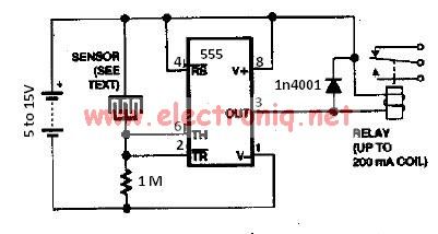 water sensor circuit using 555 timer
The water sensor circuit is based on a 555 timer circuit and come common electronic components. The water sensor is made by two metal electrodes arranged very close that a drop of water (liquid) will bridge them. If the liquid ( water ) is very pure you may change the...
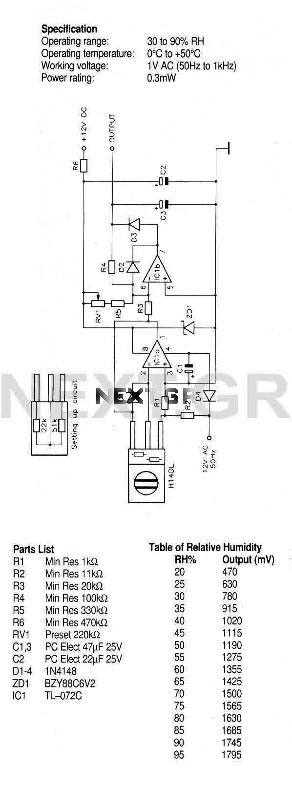 Humidity Sensor with the H14DL
A humidity sensor with temperature compensation built-in. Never apply a DC voltage to the sensor, even measuring the sensor with an ohmmeter will damage the device, always ensure that an AC voltage is applied. Avoid condensation, freezing, dust, mist, oil, alcohol, etc. To set up this circuit replace the H14DL...
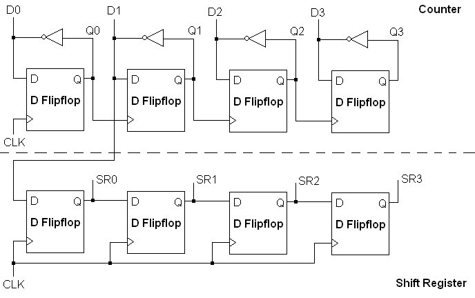
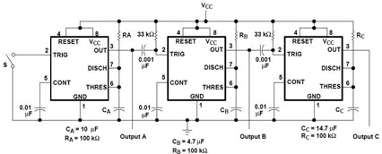 sequential timer circuit diagram using 22
A sequential timer circuit device are used in many applications for initializing conditions during start-up or for activation of test signals in sequences such in test equipment device. The circuit diagram below shows a sequencer circuit with possible applications in many sistems. As you can see, it uses the NE555...
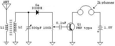 Circuit Diagram of a Crystal Radio Receiver with AF Amplification using a Germanium Transistor
The following schematic shows a Crystal Radio Receiver Circuit Diagram with AF Amplification using a Germanium Transistor. The addition of AF amplification will..
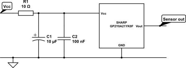 arduino Sharp IR distance sensor outputting consistently high voltage
A project with two distance sensors that signal an Arduino to operate a servo motor when an object comes into range. This currently works well, except that the sensors are outputting a relatively high voltage all the time, so I have to set a very high cutoff voltage in the...