
SD/SDHC Card Interfacing with ATmega8 /32 (FAT32 implementation)
")
The microSD card interfacing project utilizes a straightforward design to facilitate data storage and retrieval in embedded systems. The integration of a microSD card provides a cost-effective solution for expanding memory capacity, making it suitable for various applications. The SPI bus compatibility allows for efficient communication between the microcontroller and the microSD card, enhancing data transfer rates and reliability.
The use of an AVR ATmega8 or ATmega32 microcontroller serves as the core of the project, providing the necessary processing power to execute commands and manage data transactions. The choice of a 3.3V power supply, while unconventional for the MAX232, demonstrates the adaptability of the components used. The addition of pull-up resistors on the CMD/DAT lines contributes to signal integrity, ensuring stable communication with different microSD card brands.
The schematic design reflects careful consideration of component placement and electrical characteristics. The removal of series resistors was a critical update to enhance SPI performance, allowing for faster data rates essential for efficient microSD operations. The inclusion of zener diodes serves as a protective measure against potential overvoltage from programming interfaces, thereby safeguarding the microSD card and associated components.
The project's objectives extend beyond basic interfacing; it aims to provide a comprehensive understanding of data management in both raw and FAT32 formats. The implementation of routines for reading and writing data, as well as file management functions, equips users with the tools necessary to interact with the microSD card effectively. Users can explore low-level data handling, enabling them to manipulate data directly, while higher-level FAT32 functions facilitate organized data storage and retrieval.
The integration of RTC functionality enhances the project's capabilities, allowing for timestamping of files. This feature is invaluable for applications requiring data logging with time-stamped entries. The implementation of I2C communication for the RTC further broadens the project's scope, enabling synchronization with real-time events.
In summary, this microSD card interfacing project offers a robust platform for learning about embedded systems, data storage, and file management. The detailed schematic and accompanying routines provide a solid foundation for further exploration and development in the field of electronics.Here is my project on interfacing of SD Card (microSD). microSD cards are available very cheap nowadays, a great option for having a huge memory in any embedded system project. It is compatible with SPI bus, so the interfacing is easy. SD card adapters are also easily available in market, one can easily make a bread-board adapter by soldering few
pins on it. Following figures show the SD card pin-out & the bread-board adapter design by soldering 7-pins of a breakout header on the microSD adapter (Click on images for larger view). I had started this project with 1GB microSD card from SanDisk (later on tested with transcend cards also).
The microcontroller is AVR ATmega8 or ATmega32 running at 8Mhz internal clock. MAX232 is used to interface the circuit with PC for monitoring the data. A 3. 3v supply is used for powering the mega8, microSD and max232 (though the specified supply for max232 is 5v, it works comfortably at 3. 3v). 7 pins of the microSD are used here, shown in the figure of pin-out. Schematic for ATmega8 is shown here (updated on 10 May 2010, SD series resistors are removed, as they were limiting the speed of SPI bus.
51k pullups are added on CMD/DAT lines. This gives better stability with different cards. Also, two 3. 6v zeners are added to protect SD in case when the ISP programmer voltage levels are of 5v. these diodes are not required if your programmer has settings for 3. 3v output) Following is the schematic for ATmega32, with RTC (added on 17 May 2010; CS pin correction, PB4 instead of PB1, done in Mar 2014). Here two supply voltages are used, 3. 3v for SD & 5v for remaining ICs. The aim of this project was to learn interfacing of SD card and to understand the data transfer in raw format as well as in FAT32 format.
I started with raw data transfer, sending some data to any block of the microSD, reading a block of it, reading and writing multiple blocks, erasing multiple blocks. All this in raw format. I used RS232 for viewing the data read by microcontroller from SD card. The uc sends the data to HyperTerminal. Similarly, to write data to card, the data was fed thru HyperTerminal, by typing some text. Once raw data transfer achieved, I formatted the card with windowsXP (FAT32) and loaded it with some text files, directories and other files (all stored in root directory of the card).
After that I wrote the FAT32 routines to read files, get file list (using HyperTerminal again), finding the total/free memory of card. All this data is sent to HyperTerminal by the uc. Options 0 to 4 are low level functions dealing with raw data. If you use option 0, 1 or 3, you may have to reformat the card before using the FAT32 routines. Here, the multiple-block functions related to options 3 & 4 are disabled due to memory constraint as that time mega8 was used for testing and these functions are not required for FAT32 testing.
While testing with mega32, options 3 & 4 can be enabled by removing a macro (#define FAT_TESTING_ONLY) defined in SD_routines. h. Options 5 to 9 are related to FAT32. Only short file names are supported right now, 8byte name+3bytes extension. If you store a long name file in SD, it will be displayed by these routines in short name format only.
For testing these options, format the card with FAT32 file system and store some directories and text files (because text files can be read & checked thru HyperTerminal). Please put up a comment or mail me if you find a bug in the code. The updates are because of valuable suggestions & comments from the users of this code. Thanks a lot! - Real Time Clock circuit support is added for time & date entries in the files. Now the current date of file creation and file update will be entered in the FAT table (can be viewed by checking file `properties` using a PC) - Same as 2.
4, with a bug fix for RTC: `twi_init` function added to define I2C clock freq. 100K@ 16MHz (50k@8MHz). This was taking default values 🔗 External reference
Related Circuits
Microcontrollers are merely silicon wafers until programmed to perform specific tasks based on user requirements. Microcontrollers serve as the fundamental building blocks in modern electronic systems, acting as the brains that control various functions within devices. They consist of a...
After conducting experiments with a rotary encoder connected directly to keyboard switches, it was found that the keyboard controller IC (an Intel P8049AH in this case) is unable to detect pulses that are too narrow. Testing involved rotating the...
The idea to produce a standard TV PAL signal using a SVGA graphics card was born a few years ago, where cheap graphics cards with TV output were still not available. To achieve a CCIR conform TV signal with...
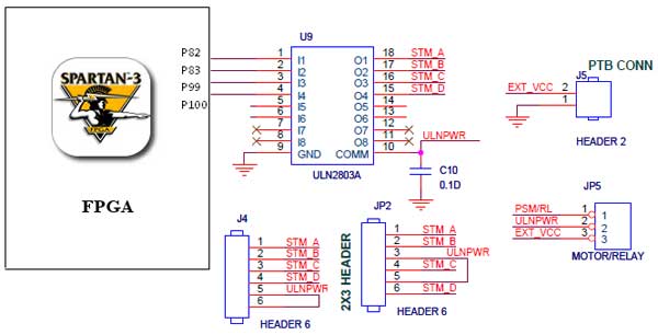
The Spartan-3 Primer board features external stepper motor interfacing, as illustrated in the accompanying figure. The stepper motor is driven by a ULN2803A, which is a high-voltage, high-current Darlington transistor array. The ULN2803 is utilized as a driver for...
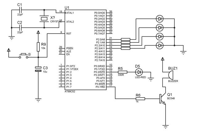
How to interface a +5V buzzer with the IC 89S52. It has been suggested to use two BC547 NPN transistors for this purpose. To interface a +5V buzzer with the 89S52 microcontroller, a common approach involves using transistors to...
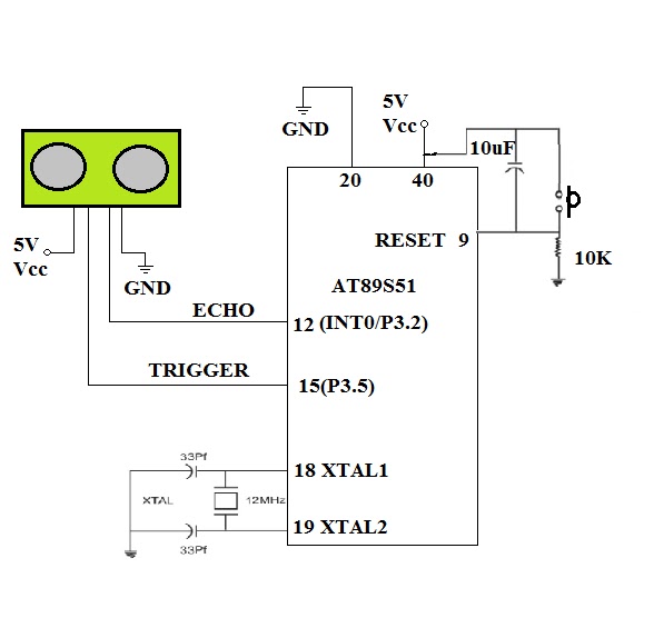
To enable a robot to detect objects in its surroundings, an ultrasonic sensor is recommended. While infrared (IR) sensors are inexpensive, their operational range can fluctuate due to ambient light changes, resulting in inaccurate range measurements. Ultrasonic sensors operate...