
Minimum Theremin Schematic
" Each IC contains six identical sections; thus the term "hex inverter. " U1sections A and B, in conjunction with R1, R2 and C1, form the theremin`s variable oscillator that operates in a frequency range around 73kHz. The antenna forms one-half of a variable capacitor that is part of this oscillator`s frequency-determining network, and the player`s hand forms the other half.
As the distance between the hand and the antenna varies, so does the capacitance, and therefore the oscillator`s frequency. U1 section C buffers the variable oscillator`s output to provide isolation from the rest of the circuit.
U2 sections A and B, in conjunction with R13, R14, RV1, and C9, comprise the theremin`s local oscillator, adjusted with the PITCH ZERO CONTROL potentiometer and ZERO CAL potentiometer RV1. RV1 is a miniature "trimmer" type, mounted on the circuit board, used to calibrate the local oscillator`s frequency range.
With RV1 properly adjusted, the local oscillator`s frequency will equal the variable oscillator`s frequency with the hand furthest away from the antenna. Under these conditions, the phase relationship of the two oscillators will be constant due to their small, but finite capacitive coupling, so no audible tone will be produced.
U2 section C buffers the local oscillator`s output to provide isolation from the rest of the circuit. The three remaining U2 sections are not used, so their inputs are grounded. The inverters` propagation delays and output impedances are supply-dependent. Accordingly, the PITCH ZERO CONTROL potentiometer affects the local oscillator`s frequency by varying its supply voltage.
This method of adjustment permits the potentiometer to be located at any convenient distance from the circuit and antenna, since frequency variations resulting from stray capacitance between the potentiometer`s slider and ground are decoupled by capacitor C8. In use, the potentiometer is adjusted by the player so that the theremin is silent with the hand furthest away from the antenna, and produces the lowest tone when the hand is at the maximum playing distance.
U1 section F, in conjunction with R3, R4, and R9, is the theremin`s mixer. The mixer "heterodynes" the two oscillator signals, producing sum and difference terms of their fundamental frequencies and harmonics. Non-linearities inherent in U1-F`s transfer function perform this operation, eliminating the diode normally used for the purpose.
C3 is a DC blocking capacitor that couples the mixer`s output to a low-pass filter consisting of R7 and C4. This filter attenuates the mixer`s inaudible heterodyne sum products, leaving the audible difference, or "beat frequency" product.
The beat frequency signal is applied to an amplifier comprised of paralleled U1 sections D and E, and gain-determining resistors R5 and R6. Capacitor C2 provides a second low-pass filtering section to further attenuate the inaudible heterodyne products.
DC is blocked from the output by C7, with R10 limiting the output current to prevent damage to U1 and R11 preventing C7 from maintaining a residual charge after power is removed. Because the theremin`s oscillators have some sensitivity to power supply variations, VR1, a low-dropout voltage regulator IC, with C5 and C6, is used to furnish a steady 5 volts.
Rectifier CR1 protects the circuit from accidental battery reversal, and R8 prevents excessive current from causing CR1 and the battery to heat under such a condition. The voltage drop across R8 is less than 200 millivolts, causing a relatively insignificant loss in battery life.
The theremin typically uses less than 2 milliamperes of current, so a 9 volt alkaline battery 🔗 External reference
Related Circuits
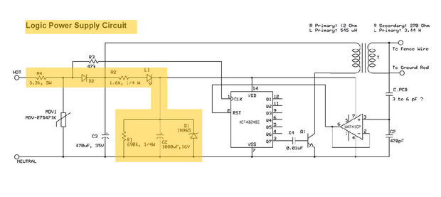
This electric fencing solution is essential for operation in regions with dry ground. It includes a schematic for an Electric Fence Charger, originally created by KC Mylrea in 1972. The purpose of this system is to power electric fences...
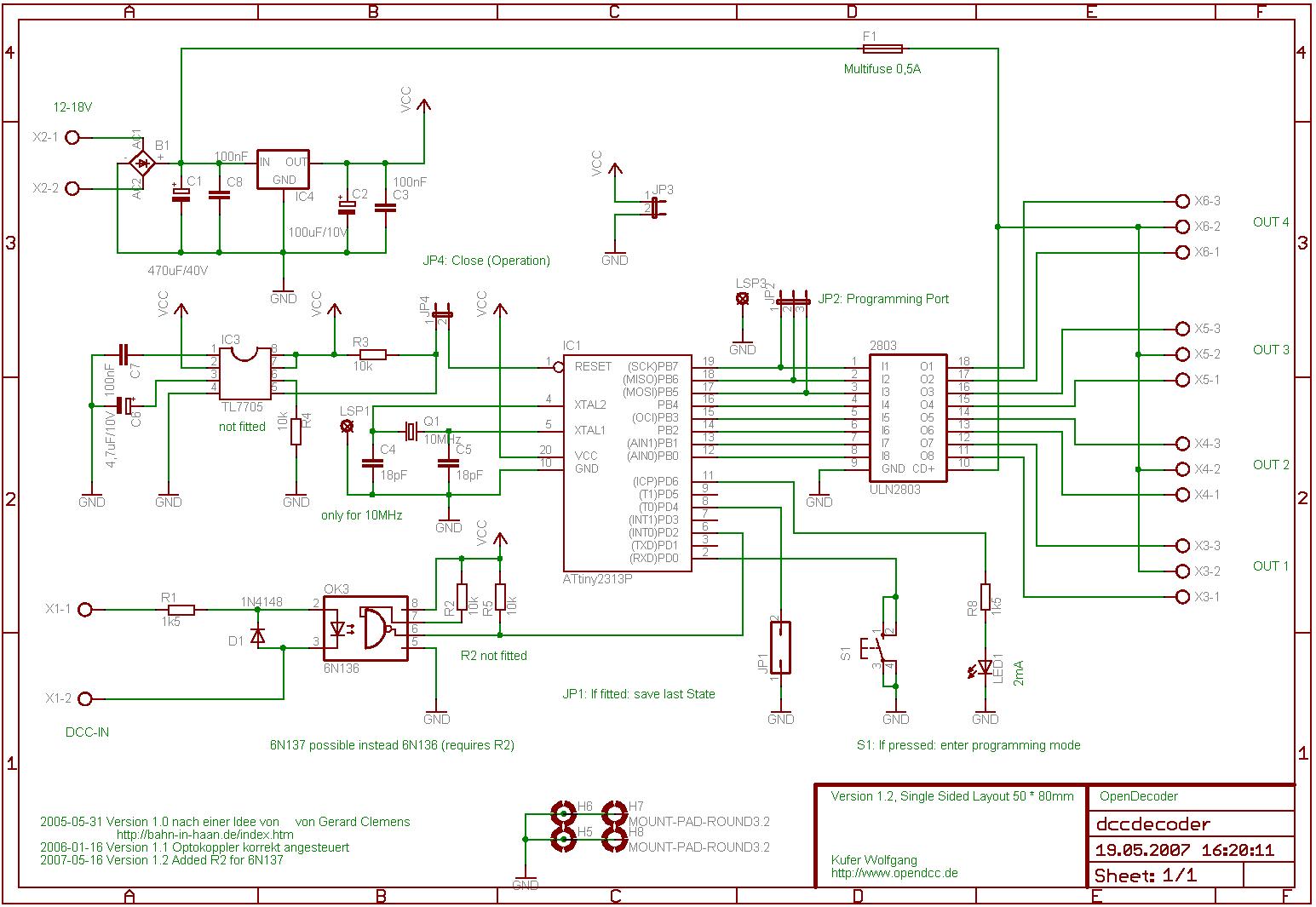
This software was developed specifically for the hardware in question. Consequently, the pin allocation of the Atmel ATtiny2313 in this circuit corresponds to the original design, allowing the software to operate on both hardware platforms. An important note is...
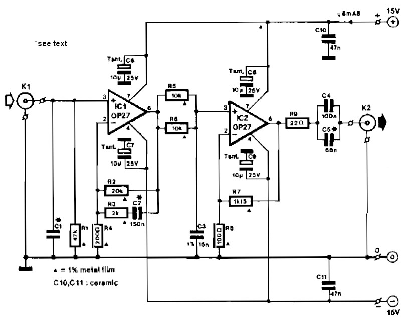
Circuit IC1 provides a gain amplification of 40 dB, which decreases to approximately 20 dB when the frequency exceeds 500 Hz. To reduce resistor noise and the load on the operational amplifier at higher frequencies, the value of resistor...
The Heater Fan Controller is designed around the PIC12F675 microcontroller. It reads a 10k linear potentiometer and generates appropriately timed pulses to control the DC motor that operates the fan. The lowest setting completely cuts off the power. This...
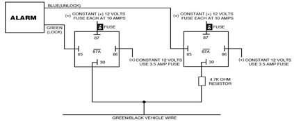
The following circuit illustrates the Ford Probe Single Wire Door Alarm System. This Single Door Locking Wire manages both LOCK and UNLOCK functions, indicating that the pulse wires must be connected to the same vehicle wire. The system primarily...

This circuit illustrates the modifications made due to a blown resistor on the backside, which was soldered in place. The issue was traced back to this specific resistor. Currently, the pattern change switch is set to Option 3, which...