
Missing pulse detector circuit using NE555

The NE555 timer IC operates in monostable mode, where it generates a single output pulse in response to an input trigger. In this application, the timer is set up to monitor the frequency of incoming pulse signals. The pickup transducer captures the relevant signal, which is then processed to produce a clean negative-going pulse. This pulse is fed into pin 2 of the NE555, which serves as the trigger input. The timing interval is determined by external resistors and capacitors connected to the IC, which define how long the output remains high after being triggered.
When the pulse frequency is above a certain threshold, the IC continuously resets the timing cycle, keeping the output low. However, if the pulse frequency decreases or if a pulse is missing, the timing capacitor begins to charge, and once it reaches a specific voltage level, the output of the NE555 transitions to a high state. This change in output can be used to signal an alarm or activate additional circuitry, thereby indicating a fault condition, such as a malfunctioning spark plug or an abnormal heartbeat.
Transistor T1 plays a crucial role in discharging the timing capacitor, allowing for rapid reset of the timing interval. The choice of components, including the timing capacitor and resistors, is critical in setting the sensitivity and response time of the circuit. This design can be further refined by adjusting the component values to suit specific applications, ensuring reliable detection of missing pulses or irregular intervals in various monitoring scenarios.An NE555 timer IC connected as shown here can detect a missing pulse or abnormally long period between two consecutive pulses in a train of pulses. Such circuits can be used to detect the intermittent firing of the spark plug of an automobile or to monitor the heart beat of a sick patient.
The signal from the pick up transducer is shaped to form a negative going pulse and is applied to pin 2 of the IC which is connected as a mono stable. As long as the spacing between the pulse is less than the timing interval, the timing cycle is continuously reset by the input pulses and the capacitor is discharged via T1. A decrease in pulse frequency or a missing pulse permits completion of time interval which causes a change in the output level.
🔗 External reference
Related Circuits
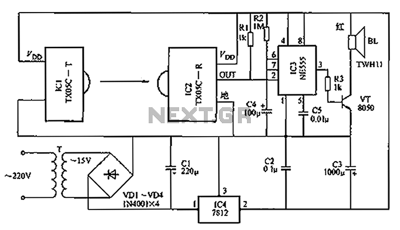
A new type of infrared system utilizes the TX05C radio sensor module for a burglar alarm designed for doors and windows. This system operates in the infrared spectrum, which is invisible to the human eye, making it suitable for...
This circuit gives out an alarm when its sensor is wetted by water. A 555 astable multivibrator is used here which gives a tone of about 1kHz upon detecting water. The sensor when wetted by water completes the circuit...
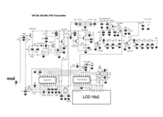
This is a straightforward high-quality PLL FM transmitter with a typical output power of 5 W and a no-tune design. It features RDS/SCA input and audio/MPX input with optional pre-emphasis and can operate with or without a stereo encoder....
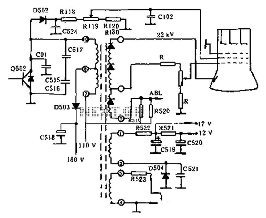
The circuit diagram of the Swallow CS37-2 type color TV illustrates the feeding tube configuration. The filament voltage is supplied by the line flyback transformer, with a current-limiting resistor R523. The accelerating voltage is managed by D502, which rectifies...
Most cards of sound in computer are deprived stereo input for microphone; on the contrary, they have stereo input for high level (Line). The circuit uses the input Line of the sound card in order to connect two mono...
This is a transistor inverter circuit diagram rated for 100 watts, designed as an easy-to-build circuit. It utilizes only transistors and does not incorporate any integrated circuits. The circuit converts a 12V battery input to a 220V, 50Hz square...