
Audio Stereo Mixer circuit

R1-8-31-32=3.3Kohms C1-4-7-9-12-17=10uF 16V IC1=TLC274
R2-7-27-30=100ohms C2-8=470nF 63V MKT IC2=TLC272
R3-4-9-10=1Mohms C3-24-27-28=100nF 63V MKT IC3=7805
R5-11-21-22-23-24=10Kohms C5-10=10pF ceramic D1=1N4007
R6-12-15-17=1Kohms C6-11=1uF 16V D2=LED 3mm
R13-14-19-20-28-29=47Kohms C13-16-20-21=47pF JF1-2-5-6=female jack 3.5mm stereo
R18-16-25-26=22Kohms C14-15-18-19=1uF 63V MKT JF3-4=RCA female plug
RV1=2X100Kohms Lin. C22-23-25=100uF 16V JF7=female jack 3.5mm mono
RV2-3=47Kohms log. C26=4.7uF 16V
RV4=2X47Kohms log. C29=470uF 25V All the resistors are 1/4W 1% metal film
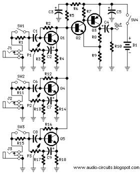
The described circuit effectively utilizes the sound card's line input to accommodate two mono microphones, enhancing its functionality for audio mixing applications. The presence of adjustable gain stages for each microphone allows for fine-tuning of audio levels, which is essential for achieving balanced sound output. The use of operational amplifiers (IC1 and IC2) facilitates signal processing, ensuring that the mixed audio maintains clarity and quality. The stabilization of voltage to +5V is crucial for protecting the sound card from potential damage due to overvoltage, thereby extending the longevity of both the sound card and the connected microphones. The component selection, including the use of metal film resistors for precision and ceramic capacitors for stability, reflects a thoughtful approach to circuit design aimed at optimizing audio performance.Most cards of sound in computer, are deprived stereo input for microphone, on the contrary have stereo input for high level [ Line ]. The circuit uses the input Line of card of sound, in order to we place a two mono stereo microphone, in the input of card of sound.
Simultaneously he is more functionnal, after we have the possibility of regulating the gain of stage of microphone and regulating the final level of sound externally and independent for each channel of microphone. This solution was selected in order to we can if we want mixing two mono microphones. Also exist the classic supply for Electret microphones. Simultaneously exist stereo input Line, with two choices plugs of input and regulation level of input with the RV4, making him mix of sounds from the microphones and the input Line, easy affair. The input A, use two plugs RCA [ JF3-4 ] and input B, use a classic stereo plug jack 3.5 mm of nail. The IC2A-B, make the addition of signals and they drive the stereo output, that becomes from the JF6 jack.
In JF7, we can give the supply, bigger than + 9Vdc, from a simple external power pack. This voltage is stabilised in + 5V, from the IC3. This low voltage was selected in order, to does not exist danger overdrive of card of sound. If the level, is not in the level that we want, we can change the prices of resistors R14-19 and R21 until R24, with other smaller or bigger, so that we change also the percentage of gain of proportional stage. Part List R1-8-31-32=3.3Kohms C1-4-7-9-12-17=10uF 16V IC1=TLC274 R2-7-27-30=100ohms C2-8=470nF 63V MKT IC2=TLC272 R3-4-9-10=1Mohms C3-24-27-28=100nF 63V MKT IC3=7805 R5-11-21-22-23-24=10Kohms C5-10=10pF ceramic D1=1N4007 R6-12-15-17=1Kohms C6-11=1uF 16V D2=LED 3mm R13-14-19-20-28-29=47Kohms C13-16-20-21=47pF JF1-2-5-6=female jack 3.5mm stereo R18-16-25-26=22Kohms C14-15-18-19=1uF 63V MKT JF3-4=RCA female plug RV1=2X100Kohms Lin.
C22-23-25=100uF 16V JF7=female jack 3.5mm mono RV2-3=47Kohms log. C26=4.7uF 16V RV4=2X47Kohms log. C29=470uF 25V All the Resistors is 1/4W 1% metal film 🔗 External reference
Related Circuits
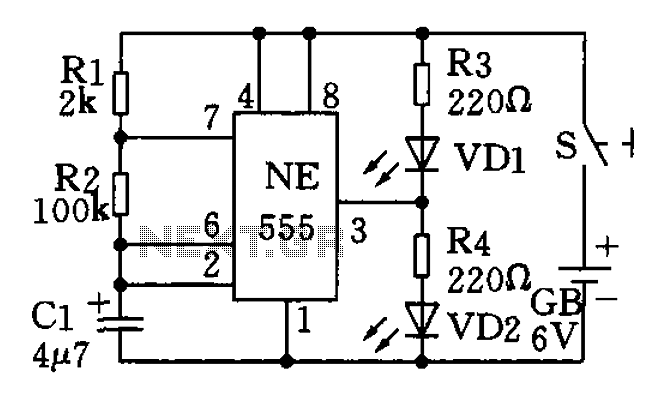
The circuit utilizes a 555 timer as the central component of a flashing light circuit. In normal operation, the light-emitting diodes (LEDs) VD1 and VD2 alternate flashing. The circuit comprises the NE555 timer, resistors R1 and R2, and capacitor...
The TDA8444 is a digital-to-analog (D/A) converter integrated circuit (IC) produced by Philips. It is designed to convert digital signals into analog signals. The TDA8444 IC utilizes a 16-pin dual in-line package, with specific pin functions and data outlined...
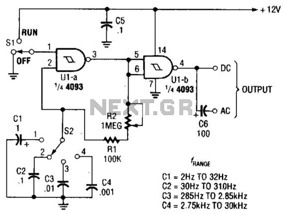
The circuit illustrated operates within a frequency range of 2 Hz to 30 kHz. Additionally, R2 is configured as either a linear or logarithmic potentiometer. The circuit is designed to accommodate a wide frequency spectrum, making it suitable for various...
The following circuit illustrates a Mini Audio Mixer with Level Control Circuits. Features include switchable high/low sensitivity, providing high performance. The Mini Audio Mixer circuit is designed to facilitate the mixing of multiple audio signals while allowing for level control...
This is a 100 Watt inverter circuit designed with a minimal number of components. The circuit utilizes the CD4047 integrated circuit from Texas Instruments to generate 100 Hz pulses, and it employs four 2N3055 transistors to drive the load....
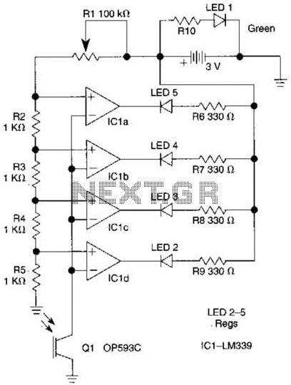
The outputs from the comparators will transition, in sequence, from high to low as the input voltage exceeds the reference voltage applied to each comparator. The output LEDs will activate sequentially as the voltage increases. The inverting inputs of...