
mixer

The microphone preamp utilizes the LM837 low-noise audio op-amp from National Semiconductor. The first stage is a fixed non-inverting gain stage with 26dB gain. A 33pF capacitor is included in the feedback loop to mitigate the LM837's tendency to oscillate, as it has a large bandwidth of 17MHz. To protect the amplifier from large voltage transients, two 5.1V Zener diodes are connected back-to-back across the input. The following stage is an inverting variable gain stage with a range of -60dB, incorporating a 47pF capacitor across the gain-control resistor. A high-quality potentiometer is recommended to avoid crackling noises, and the wiring should be tightly twisted and shielded to minimize noise and mains hum pickup. The final stage is an inverting buffer (unity gain) that corrects the inversion caused by the variable gain stage.
The mixer is constructed as a fixed-gain summing amplifier based on the LM837, which combines the signals from the six microphone preamps into a single output called MIX OUT, accessible via a rear-panel socket. This output is then split into two outputs for easy connection to external stereo equipment, allowing for the integration of external effects units or graphic equalizers between the mixed output and the power amplifier. A clipping monitor provides a visual indication of clipping occurrences in any input channel. The circuit is replicated for each channel, utilizing a potentiometer to select a clipping voltage for comparison, adjusted to 2V. This setting indicates clipping when the input exceeds 2V, which may lead to clipping in a line-level output. However, it is important to note that clipping may still occur at the final output if the summed voltages from all inputs exceed 2V. The outputs of the LM339 are open-collector, connected to the +12V supply dedicated to the LEDs, preventing LED switching noise from affecting the op-amp power supply. A 10µF capacitor is placed across the LED to provide a persistence effect, allowing users to detect momentary clipping excursions. The combination of a 100µF and a 330µF capacitor acts as a low-pass filter, preventing switching currents from contaminating the supply line.
The input mixer consists of two 2-input mixers, similar to the six-input mixers previously described. These mixers combine the LINE-IN and AUX inputs while maintaining separate left and right channels. LINE-IN is designated for effects return, while AUX-IN accommodates any external line-level inputs, such as tape decks or computer audio outputs. The stereo output from the input mixers feeds into the tone/volume/balance circuit. For simplicity, the LM1036 tone/volume/balance chip is employed for this section of the mixer, following the configuration outlined in the LM1036 datasheet. The balance input has been disabled using a pair of fixed resistors to provide a DC voltage of VCC/2. The choice to utilize the LM1036 is justified by its effectiveness in achieving the desired functionality without unnecessary complexity.It`s a relatively straightforward design, and will probably not be the best way of doing this. However, it works fairly well, and is relatively inexpensive to build. Six independent microphone amplifiers with up to 60dB gain (theoretical, not tested). Each channel has an independent fader and an attenuator to allow connection of musical instruments which have line-level outputs (such as synthesizers). Two stereo line-level inputs are provided, line-in (effects-receive) and aux-in. These are mixed together (no faders available, though), and sent to the next stage. Master volume and tone control, based on the National Semiconductor LM1036. This chip allows stereo volume and tone controls, without using expensive and unreliable ganged potentiometers. The mike preamp itself is based on the LM837 Low-noise audio opamp from National Semiconductor. The first stage is a noninverting 26dB gain stage (fixed). Note the use of the 33pF capacitor in the feedback loop, this reduces the tendency of the LM837 to oscillate (it has a large bandwidth of 17MHz).
Two 5. 1V Zener diodes are connected back-to-back across the input, to protect the amplifier from large voltage transients at the input. The next stage is an inverting variable gain stage (- to 60dB), again with a 47pF capacitor across the gain-control resistor.
The pot used here should be of high-quality to prevent crackling, etc. Also, the wires should be tightly twisted and shielded to prevent noise and mains-hum pickup. The last stage is an inverting buffer (unity gain), to correct the inversion caused by the variable gain stage. The mixer itself is a fixed-gain summing amplifier based on an LM837. It sums up all the six microphone preamp signals into a single output. This is called the MIX OUT, and is a rear-panel socket. The single output is split into two outputs, to allow easy connection to external stereo equipment. The idea behind this is to allow connection of an external effects unit or graphic equalizer between the mixed output and the power amplifier.
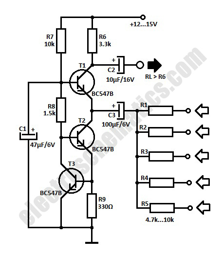
The clipping monitor is used to give a visual indication of when clipping occurs, in any of the input channels. The circuit shown is repeated for each channel. A potentiometer is used to select a clipping voltage to compare the inputs with, it should be adjusted to 2V.
This will then give a clipping indication when the input crosses 2V, which would cause clipping in a line-level output. Of course, this does not mean that clipping wont occur at the final output, since the summed voltages from all the inputs can exceed 2V.
The outputs of the LM339 are open-collector, so I`ve connected the output to the +12V supply, which is used only for the LEDs. This ensures that LED switching noise does not get into the power supply of the opamps. Note the use of a 10 µF capactor across the LED, this gives a persistence effect to the LED, allowing the user to detect momentary clipping excursions.
The 100 µF/330 © combination acts as an LPF, preventing switching currents from getting onto the supply line. The input mixer is a pair of 2-input mixers, similar to the six-input mixers shown above. These mix together the LINE-IN and AUX inputs, keeping the left/right inputs seperate. LINE-IN is meant for the effects-return line, while any external line-level inputs such as tape decks, computer audio outputs, etc.
can be connected to the AUX-IN. The stereo output of the input mixers is given to the tone/volume/balance circuit. For simplicity, I`ve used the LM1036 tone/volume/balance chip to do this part of the mixer. The circuit is straight out of the LM1036 datasheet. In my mixer, I disabled the balance input by using a pair of fixed resistors to give it a DC voltage of VCC/2 Using the LM1036 may seem like laziness or a cop-out, but there`s a good reason for using 🔗 External reference
Related Circuits
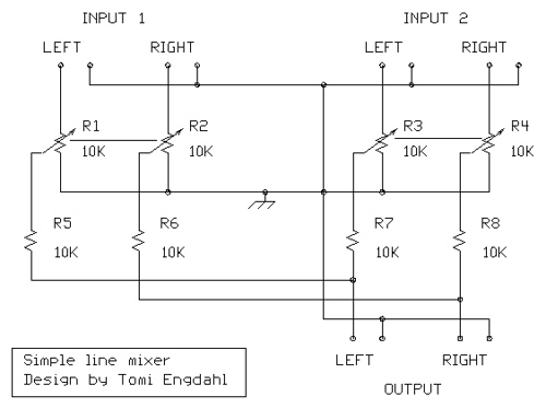
The simple audio mixer circuit is built on the common base principle, where input voltages are transformed into alternating currents which are summed to form the output. The simple audio mixer circuit utilizes a common base configuration to achieve effective...
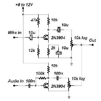
This two-channel audio mixer utilizes 2N3904 transistors to create two preamplifiers. The first preamplifier is designed for high gain, suitable for microphone input, while the second preamplifier allows for control over the audio level input. The audio mixer requires...
If two of these circuits are made in the same enclosure for stereo, then there can be a single power supply to run both of them. There should be a resistor in series with the incoming 9V+ lead so...

The SA607 is a low voltage, high-performance monolithic FM intermediate frequency (IF) system that includes a mixer, oscillator, two limiting intermediate frequency amplifiers, a quadrature detector, a logarithmic received signal strength indicator (RSSI), a voltage regulator, and audio and...
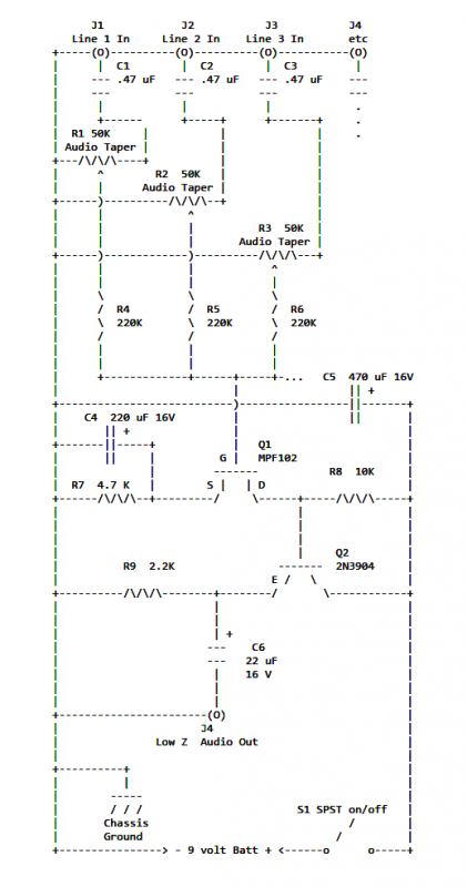
The mixer circuit described features three line inputs and three microphone inputs. The microphone inputs are designed for low impedance dynamic microphones with a range of 200 to 1000 ohms. Alternatively, an electret condenser microphone (ECM) can be used,...
TX OpAmps TX Mixer (QSE) PTT RX Switching PA/Filters External Connections Comments Revisions WB5RVZ SDR Home. This stage integrates the TX Mixer into the board, allowing for the modulation of the Dividers' output signals by the four I and...