
mixer translates multiple standards

The described broadband frequency-upconversion mixer represents a significant advancement in the field of wireless communications, particularly for applications requiring compatibility with multiple standards. The design employs a cross-coupling post-distortion technique, which enhances linearity while maintaining low power consumption, a critical requirement for modern wireless transmitters. The use of a CHRT 0.18-µm silicon CMOS process facilitates integration and miniaturization, making the mixer suitable for compact devices. The achieved specifications, such as a maximum IIP3 of +16.56 dBm and a noise figure of 10.7 dB, demonstrate the device's capability to operate effectively across a broad frequency range. The low power consumption of 5 mW from a +1.2-VDC supply further enhances its appeal for battery-operated devices and energy-efficient systems.
The integration of linearization techniques, such as the cross-coupling post-distortion method, addresses the inherent trade-offs between linearity and other performance metrics, allowing for improved performance in challenging wireless environments. This mixer is particularly beneficial for software-defined radios and ultrawideband communications, where versatility and performance are paramount. The development of such advanced upconversion mixers is essential for the ongoing evolution of wireless communication technologies, enabling devices to meet the demands of diverse applications and communication standards.This broadband frequency-upconversion mixer, which has been simulated with and without a novel linearity-enhancement circuit, is suitable for multiple-standard wireless applications from 1. 0 to 10. 6 GHz. Wireless communications products continue to support multiple communications standards, pushing designers to develop components that can work acr
oss as many bands and standards as possible. Ideally, a single device would handle all wireless communications standards and bands. But before that day comes, it is necessary to develop components ”such as upconversion mixers ”that can operate with several wireless standards. By employing a cross-coupling post-distortion technique (CCPFT), it was possible to design an upconversion mixer with outstanding linearity for multiple wireless communications standards.
The mixer was simulated with commercial software, based on fabrication with a CHRT 0. 18- m silicon CMOS mixed-signal/RF semiconductor process. As will be shown, the mixer consumes only 5 mW power from a +1. 2-VDC supply. It achieves a maximum input third-order intercept point (IIP3) of +16. 56 dBm with 3. 5 dB conversion gain (flat to within ±0. 5 dB), with 10. 7-dB noise figure (flat to within ±0. 5 dB) across a frequency range of 1. 0 to 10. 6 GHz. This makes it ideally suited for software-defined radios (SDRs), as well as multiple-band ultrawideband (UWB) communications systems. 1 An upconversion mixer should provide low noise figure with reasonable gain and high linearity while consuming low power to be effective in modern multiple-standard wireless transmitters.
Such mixers have been developed, including the 3. 0-to-5. 1-GHz upconversion mixer of ref. 2 designed with a current-reuse technique to minimize power consumption. It delivers 3. 8-dB gain and 8. 4-dB noise figure, but only ’7. 6-dBm IIP3. In ref. 3, a 1. 0-to-11. 0-GHz upconversion mixer was proposed, with an adopted fold structure and inductor-free matching network. Although its IIP3 reaches +12 dBm, the conversion gain is below 0 dB ( ’6 dB). In ref. 4, a 3. 0-to-5. 0-GHz upconversion mixer with current-reuse bleeding technique was presented. It achieves 6. 5-dB conversion gain and IIP3 of +11. 6 dBm. However, its power dissipation is 11. 0 mW, and the mixer has a very complicated structure. In ref. 5, a 6. 0-to-8. 0-GHz upconversion mixer was proposed which uses a feedback loop in its transconductance stage. It achieves 0-dB conversion gain and 7. 0 dB noise figure, but its linearity is not mentioned. From these reference examples, it is apparent that tradeoffs were made between linearity and other performance parameters.
For high upconversion-mixer linearity without sacrificing the other key mixer performance parameters, it is necessary to apply some linearization techniques. Numerous circuit linearization techniques have been developed for low-noise amplifiers (LNAs). One commonly used method is the derivative superposition technique. 6, 7 It employs auxiliary transistors biased via weak inversion, which produces a nonlinear current to cancel out the third-order intermodulation generated by the main transistors.
This approach is mainly effective at lower frequencies and can induce additional gate noise. Recently, a post-distortion technique8 and a cross-coupling post-distortion technique9, 10 were implemented for LNA linearization. Both methods yielded IIP3 performance levels exceeding +10 dBm without seriously degrading the other key LNA parameters.
For multiple-standard wireless communications applications, a low-voltage upconversion mixer was developed using a pseudodifferential double-balanced structure, allowing for high isolation between ports while operating with low supply voltage. It also employs a current-bleeding topology for improved noise and linearity performance. 11 A cross-coupling post-distortion technique was also adopted to further improve IIP3. The added linearization circui 🔗 External reference
Related Circuits
A stomp-box was designed and built for Grammy-winning resophonic guitar player Stacy Phillips. He typically uses two transducers on his Dobro-style instruments: a piezo element mounted internally and a gooseneck-mounted electret microphone positioned approximately one inch above the resonator...
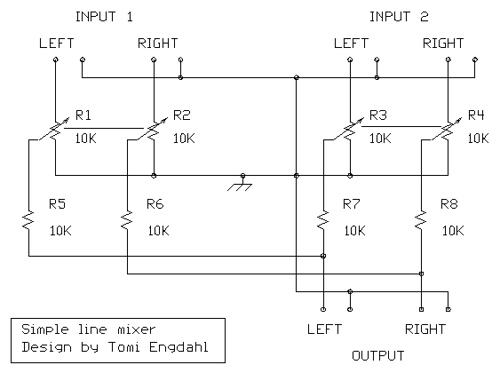
Most sound cards in computers lack stereo input for microphones, but they do have stereo inputs for high-level signals (Line). This circuit utilizes the Line input of the sound card to connect two mono microphones to the sound card's...
A current differencing transconductance amplifier (CDTA) serves as an active component that can be utilized to create various filter responses. The selection of different filter characteristics is achieved by altering the bias current supplied to the amplifier. The current differencing...
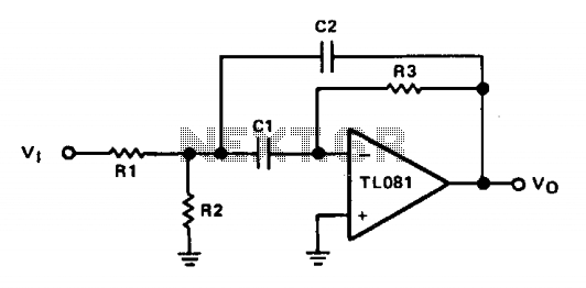
The operational amplifier (op amp) is configured in inverting mode. Resistor R3 connects the output to the inverting input, establishing the gain and the current through the frequency-determining capacitor, C1. Capacitor C2 provides feedback from the output to the...
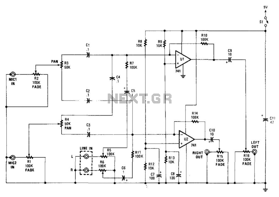
This stereo mixer features two mono mixers and a modification to the microphone inputs. When a microphone is in use, its output is directed to the microphone input of the circuit. The signal is then processed through resistors R1...
The mixer circuit described features three line inputs and three microphone inputs. The microphone inputs are designed for low impedance dynamic microphones with a range of 200 to 1000 ohms. Alternatively, an electret condenser microphone (ECM) can be used,...