
Mixing analog multiplier integrated circuit MC1496

The described communications receiver employs advanced mixing techniques to ensure high fidelity in signal processing. The diode ring mixer is essential for its ability to efficiently combine signals, while the double differential pair balanced modulator enhances linearity and minimizes distortion. The MC1496 analog multiplier serves as the core component for mixing, allowing for precise control over modulation and demodulation processes.
The configuration of the 50 kΩ potentiometer plays a critical role in fine-tuning the local oscillator voltage and input signal voltage, which are pivotal for optimizing the receiver's performance. The foot DC potentiometer is employed to establish a zero reference point, ensuring that any potential DC offsets do not adversely affect the signal integrity.
Interference and noise signals can significantly degrade the quality of the received signal. The design anticipates these challenges by allowing for adjustments that help mitigate their impact. The combined frequency generated by the interaction of the input and local oscillator signals can lead to unwanted frequency components. If these components align with the intermediate frequency, they can introduce additional noise into the system.
The intermediate frequency amplifier is tasked with amplifying the desired signal while filtering out unwanted frequencies. The subsequent demodulator processes this amplified signal, preparing it for output. The output stage is crucial, as it must deliver a clean signal while minimizing interference. The primary concern is the intermediate frequency interference and mirror interference, which can distort the demodulated output.
Finally, the extraction of the 9 MHz IF signal from the single-ended output is accomplished using a bandpass filter, which selectively allows the desired frequency to pass while attenuating others. This filtering step is essential for maintaining the integrity of the received signal, ensuring that the output is as clear and accurate as possible. The overall design reflects a sophisticated approach to high-quality communication receiver architecture, addressing the complexities of signal mixing and interference management.Currently, high-quality communications receiver in the use of diode ring mixers and mixer by a double differential pair balanced modulator constituted, set into an analog multiplier (MC1496) shown in Figure mixer circuits. LO voltage HL and the input signal voltage input from the input channel hoppers were adjusted 50kfl potentiometer, O, foot DC potentiometer zero. In addition to acting on the mixer input signal voltage and the local oscillator voltage Sapporo soul, but also the presence of interference and noise signals.
Between any two of them are likely to produce the combined frequency, if the frequency of the combined signal is equal to or close to an intermediate frequency, the input signal - in time through intermediate frequency amplifier, a demodulator, the output stage produces interference, the influence of the received signal, inevitably to cause interference, in which the greatest impact is the intermediate frequency interference and interference mirror. IF signal (9MHz) removed from the single-ended output foot after Ji bandpass filter.
Related Circuits
Many households still have tube-type television sets. Connecting one of these large televisions to a stereo system to enhance sound quality is generally straightforward, as numerous SCART to Cinch adapters are available in accessory stores. However, some television sets...
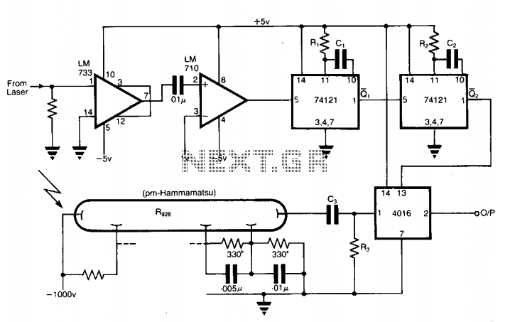
The application involves observing the light pulse emerging from a thick specimen after transillumination by a laser pulse. Pulses derived from the laser source are amplified using a Video Amplifier LM733. The reference level is set to 1 V...
This design note presents a simple yet feature-rich 16-watt output, universal AC input adapter power supply for modems, hubs, or similar applications. The circuit utilizes a discontinuous mode (DCM) flyback converter topology designed around ON Semiconductor's NCP1027 monolithic current...

This design outlines a door alarm circuit that utilizes an electronic system. It features a synthesized sound chip from Holtek, specifically the HT-2811, which reproduces the sound of a "ding-dong" chiming doorbell. The circuit also incorporates a CMOS 4026...
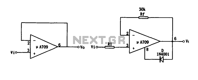
Figure (a) illustrates a voltage follower circuit, which serves as a specific instance of an in-phase amplifying circuit. The input signal originates from an integrated operational amplifier. At the conclusion of the introduction phase, the feedback resistor is set...
The gate-source voltage required to bias the transistor into the linear region can range from 0.25V to 8V, resulting in a potential variation of 7.75V down to a minimal 0.4V for the transistor and load when used with a...