
mobile incoming call indicator

The circuit operates by detecting the electromagnetic field generated by the mobile phone during an incoming call. The design utilizes a simple yet effective method of induction, where the coil L1 acts as an antenna to capture the high-frequency signals emitted by the phone. The captured signal is then amplified by transistor Q1, which is configured as a switch. When the signal is strong enough, it turns on the transistor, allowing current to flow from the power supply through the LED connected to the NE555 timer's output.
The NE555 timer is configured in monostable mode, where it is triggered by the rising edge of the signal from Q1. The output at pin 3 of the NE555 will go high for a duration determined by the resistor and capacitor connected to the timer, causing the LED to blink. This blinking serves as a visual alert to the user, indicating that a call is incoming.
For the construction of coil L1, precision in the number of turns and the wire gauge is critical, as these factors influence the coil's inductance and its effectiveness in capturing the desired frequency. The choice of a 10 µH coil can also simplify assembly for those who prefer not to wind their own coil, ensuring consistent performance.
Overall, this circuit is an innovative solution for individuals seeking to minimize disturbances from mobile phone rings at home while still being alerted to incoming calls.This circuit can be used to escape from the nuisance of mobile phone rings when you are at home. This circuit will give a visual indication if placed near a mobile phone even if the ringer is deactivated. When a call is coming to the mobile phone, the transmitter inside it becomes activated. The frequency of the transmitter is around 900MHz. The co il L1 picks up these oscillations by induction and feds it to the base of Q1. This makes the transistor Q1 activated. Since the Collector of Q1 is connected to the pin 2 of IC1 (NE555), the IC1 is triggered to make the LED connected at its output pin (pin 3) to blink. The blinking of the LED is the indication of incoming call. The coil L1 can be made by making 150 turns of 36 SWG enameled copper wire on a 5mm dia plastic former.
Or you can purchase a 10 uH coil from shop if available. 🔗 External reference
Related Circuits
The reason for this project was to facilitate a quick installation for a local friend 10 km away, enabling the start of real-life testing to identify and resolve bugs and problems before releasing it to other users. The software...
The i-TRIXX circuit is designed to prevent issues for individuals traveling in a caravan. It provides an early warning system through an illuminated LED, alerting users when the battery charge is low, thereby preventing the inconvenience of being unable...
Quiz-type game shows are increasingly popular on television. In these games, fastest finger first indicators (FFFIs) are used to test players' reaction times. When a player presses their entry button, their designated number is displayed alongside an audio alarm....
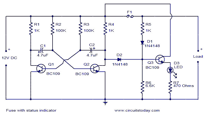
The circuit diagram presented illustrates a fuse with an automatic status indicator, designed for operation with a 12V DC supply. While the fuse remains intact, the LED D3 emits a continuous glow; however, if the fuse blows, the LED...
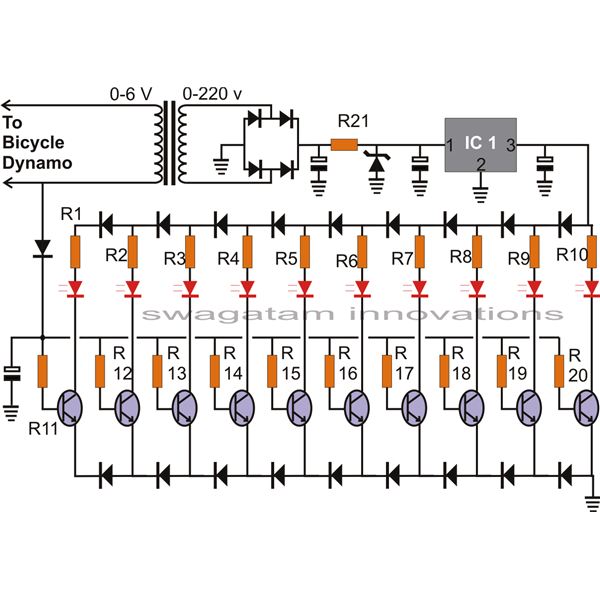
The article presents a circuit that can be used for indicating the riding speed of a bicycle. The bicycle speedometer circuit explained here utilizes standard components such as transistors and LEDs to effectively display a clear 10-step, accurately calibrated...
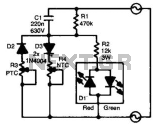
For the absolute measurement of temperatures, a thermometer is essential. However, in many situations, an absolute value is not required, and a relative indication suffices. It would be advantageous if a green light indicated that the temperature is within...