
Fuse with status indicator

The circuit operates on a 12V DC supply, making it suitable for various automotive and electronic applications. The astable multivibrator, formed by transistors Q1 and Q2, generates a square wave output that toggles between high and low states. This oscillation is crucial for the blinking function of the LED, providing a visual indication of the fuse status.
In the circuit, when the fuse is functional, the continuous current flow through the LED D3 is maintained, indicating normal operation. The inclusion of diode D2 ensures that the output from the astable multivibrator does not interfere with the biasing of Q3 when the fuse is intact. Resistor R5 plays a vital role in establishing the base current for Q3, ensuring it remains in the conductive state.
Upon fuse failure, the absence of a positive voltage at the base of Q3 leads to a change in its operating state. The astable multivibrator's output now becomes the primary control signal for Q3. This configuration allows Q3 to switch on and off rapidly, resulting in the blinking of LED D3. The rate of blinking is determined by the time constants associated with the capacitors and resistors in the multivibrator circuit, which can be adjusted to suit specific application requirements.
Overall, this circuit design provides an effective method for monitoring fuse integrity through a simple visual indicator, enhancing safety and reliability in electronic systems. The implementation of an automatic status indicator for fuses can be particularly beneficial in applications where immediate feedback on fuse condition is critical.Here is the circuit diagram of a fuse that has an automatic status indicator. This circuit can be added to circuit that operates from 12V DC. As long as the fuse is intact, the LED D3 will glow continuously and when the fuse blows off the LED will start and continue blinking. The first part of the circuit includes an astable multivibrator built ar ound transistors Q1 and Q2. The output of the multivibrator is coupled to the base of Q3 via diode D2. When the fuse is intact the base of Q3 will be pulled to a positive voltage by the resistor R5. The transistor will be ON and the LED D3 remains glowing. When the fuse of blown off, the base of Q3 will no longer be pulled to positive voltage and now the only biasing available at the base of Q3 will be the output from the astable multivibrator. Now the transistor Q3 will start switching in the frequency of astable multivibrator and the LED will blink in accordance.
🔗 External reference
Related Circuits

The LED is normally lit, but it will be briefly extinguished if the input exceeds a preset level (set by RV1). A possible application is to monitor the output voltage across a loudspeaker; the LED will flicker with large...
A peak level indicator is a device that signals when a signal surpasses a specific maximum value. It proves to be particularly beneficial in applications such as tape recorders and mixing consoles. A crucial requirement for a peak level...

A method of adding overload protection to a power supply using a relay is shown. In each circuit, the relay must be reset by a momentary switch using a charge on capacitor C2. This prevents overload if the short...

When the water level is below the steel rods, there is no contact between the metal can and the rods, which are supported by a small insulated wooden board. The small circuit built around IC1 does not draw any...

This circuit utilizes two pairs of comparators from an LM339N quad comparator. One pair controls the yellow positive (+) and negative (-) indicators, while the other pair drives the red warning LED3. The circuit is powered by the unregulated...
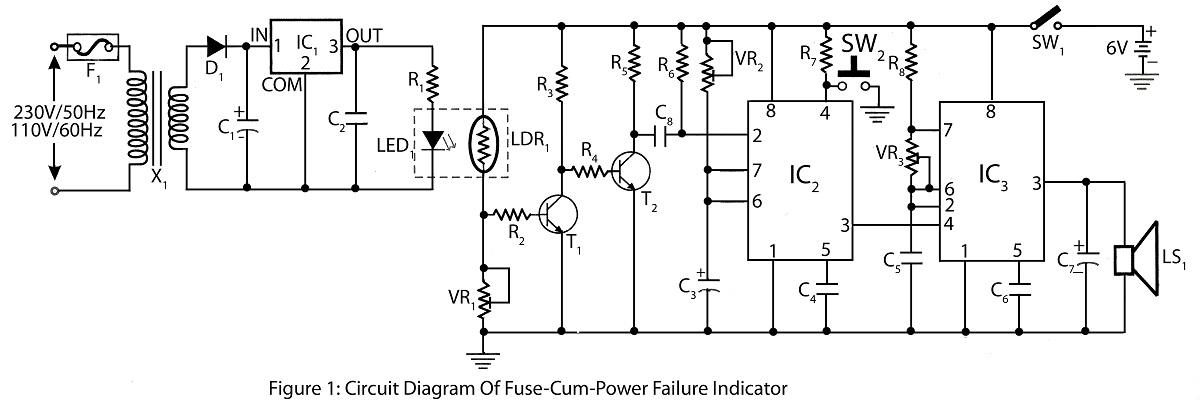
The Fuse Cum Power Failure Indicator utilizes a thermistor and a timer IC (NE555) in its circuit design. The circuit diagram includes a parts list for the fuse cum power failure indicator, which signals instances of power failure. The Fuse...