
Mobile Phone Travel Charger

The mobile charger circuit is designed to be compact and portable, making it suitable for travel. It primarily consists of a battery holder for 1.5-volt pen cells, a voltage regulator, and a charging connector compatible with mobile phones. The circuit can accommodate multiple pen cells connected in series to achieve the necessary voltage output, typically 5 volts, which is required for charging most mobile devices.
The charger begins with the insertion of the pen cells into the holder, ensuring correct polarity to avoid damage to the circuit. The combined output voltage from the cells is then fed into a voltage regulator, such as the LM7805, which stabilizes the output to a consistent 5 volts. This regulator is essential for protecting the mobile phone from voltage fluctuations that could potentially harm its battery.
Additionally, a charging connector, such as a Micro USB or USB-C, is integrated into the design, allowing for easy connection to various mobile phone models. To enhance safety and efficiency, a diode may be included in the circuit to prevent reverse current flow, which could discharge the pen cells when the charger is not in use.
The performance of this charger allows for multiple recharges of a mobile phone battery, making it a reliable option for users on the go. The simplicity of the circuit also facilitates easy assembly and troubleshooting, making it accessible for hobbyists and engineers alike. Overall, this mobile charger provides a practical solution for maintaining device power during travel.Here is an ideal mobile charger using 1.5 volt pen cells to charge mobile phone while traveling. It can replenish cell phone battery three or four times in.. 🔗 External reference
Related Circuits
In order to achieve a status between two levels of switching for two calls at the same time, you must first establish privacy on each call. Otherwise, you will end up with all four phones talking to each other,...
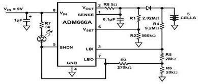
The ADM666A application note provides a detailed explanation of a low-cost battery charger circuit, including maximum output voltage, charge termination voltage calculation, battery voltage level monitoring, and circuit efficiency optimization. The ADM666A utilizes an NPN transistor and a P-channel...
The transmitter for the wireless headphones is built around a CD4046 CMOS phase-locked loop, coupled with a driver transistor, and a pair of infrared LEDs. More: Although the CD4046 is comprised of two phase comparators, a voltage-controlled oscillator (or...
Here we use the PIC16711. Rechargeable battery capacity is rated in mAH (milliampere-hours). The total capacity of a battery is defined as "C", that is it can supply C mA for 1 hour, or 2C for 30 minutes etc....
In older amps is usually a phono input. Today, this used less and less, and it would be useful if the input and line input can be used. This circuit goes. The circuit is actually an attenuator and a...
With this circuit mounted in or near every phone in the house, it will allow users to know if the phone is being used and not to pick up the phone. When a phone is taken off hook, the...