
Model Theatre Lighting Dimmer

This circuit design incorporates a dimmer functionality specifically tailored for a model theatre lighting system, employing touch globes as the primary illumination source. The core component of the circuit is a 55, which likely refers to a specific integrated circuit or component number that is pivotal in regulating the voltage and current supplied to the touch globes.
The dimming feature is achieved through a pulse-width modulation (PWM) technique or a phase-cut dimming method, depending on the specific implementation of the circuit. This allows for smooth transitions in brightness levels, accommodating various theatrical scenarios and enhancing the overall visual experience.
The circuit may include additional elements such as resistors, capacitors, and possibly transistors to manage the current flow and ensure stable operation. A microcontroller could also be integrated to provide advanced control features, such as remote dimming capabilities or programmable lighting sequences.
Power supply considerations are critical, as the circuit must handle the input voltage and current requirements of the touch globes while maintaining safety and efficiency. Proper heat dissipation methods, such as heat sinks or thermal management strategies, should be implemented to prevent overheating of components during prolonged use.
Overall, this circuit is designed to provide reliable and adjustable lighting control, making it an essential part of the model theatre's lighting system, enhancing both functionality and aesthetic appeal.This circuit is the basis for the dimmers in a model theatre lighting system which uses touch globes as the light source. The circuit is based around a 55.. 🔗 External reference
Related Circuits
This application note outlines the development and implementation of a Digital Weigh-Scale (DWS) utilizing Zilog's Z8 Encore! Microcontroller. The reference design provides a ready-to-use DWS solution that is easily scalable for measuring high-capacity loads. An external high-resolution Analog-to-Digital Converter...
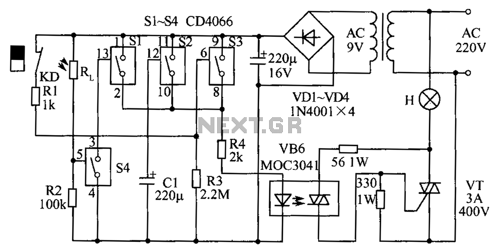
The circuit diagram illustrates a group of four analog electronic circuit switches (S1 to S4). Switches S1, S2, and S3 are utilized in a parallel delay circuit. When the power is activated, resistor R4 drives the triac VT, which...
The VRbot is a voice recognition module featuring multiple functions. Its dimensions are approximately 1" x 1.75". The manufacturer offers a free GUI software called VRbot GUI for setting up user-defined commands. Since the input/output data for the VRbot...
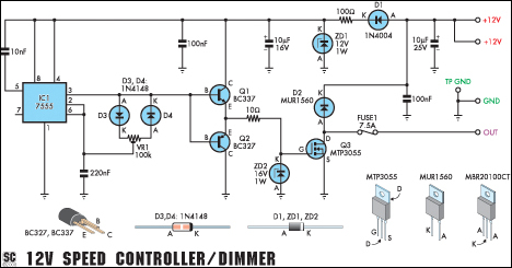
This versatile circuit functions as a speed controller for a 12V motor with a continuous rating of up to 5A or as a dimmer for a 12V halogen or standard incandescent lamp with a maximum rating of 50W. It...
Quiz-type game shows are increasingly popular on television. In these games, fastest finger first indicators (FFFIs) are utilized to assess players' reaction times. When a player presses their designated entry button, their number is displayed along with an audio...
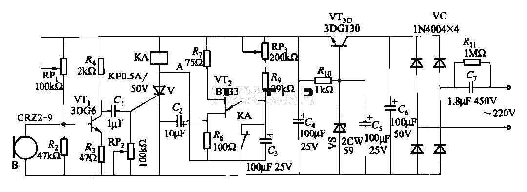
The circuit features voice switches with Figure 2109. It utilizes a single-junction transistor (VT2) and RC components to create a delay. The delay time can be adjusted using the potentiometer (RP3) or the capacitor (C3). The described circuit employs a...