
Three thyristor switch voice lighting circuits

The described circuit employs a single-junction transistor (VT2) as the primary switching element, which is pivotal in controlling the voice activation mechanism. The inclusion of resistive (R) and capacitive (C) components forms an RC delay circuit, which is essential for managing the timing of the voice switch activation.
The adjustment potentiometer (RP3) allows for fine-tuning of the delay time, providing flexibility in operation according to specific application requirements. By altering the resistance, the charge time of the capacitor (C3) can be modified, thus changing the time it takes for the circuit to respond after the voice activation signal is received.
The capacitor (C3) plays a crucial role in determining the delay duration; a larger capacitance will result in a longer delay, while a smaller capacitance will yield a shorter delay. This adjustable delay feature is particularly useful in applications where precise timing is critical, such as in automated voice-activated systems or in scenarios where a delay is necessary to prevent false triggering from ambient noise.
Overall, the combination of the single-junction transistor, RC components, and adjustable elements provides a versatile and effective solution for implementing voice-activated switching in electronic circuits.Features voice switches with Figure 2109. From single-junction transistor VT2 and RC components delay the circuit. Adjustment potentiometer RP3 or capacity capacitor C3 can cha nge the delay time.
Related Circuits
Built around an LM380, this amplifier includes tone controls and electronic "soft switching". The soft switching circuitry ensures power is built up gradually eliminating the dc thump. The soft switching is enabled by a BD131 transistor wired as a...
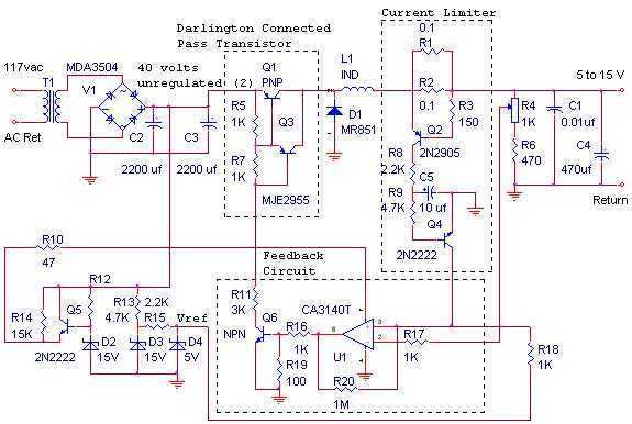
The switching power supply, shown in the schematic, provides 12 volts, at 10 amps, maximum, using a discrete transistor regulator with an op-amp functioning as a comparator in the feedback circuit. The supply was constructed in 1984 and is...
Some time ago, an electronic hobbyist sought to create a logic analyzer. As a DIY enthusiast, a simple yet effective logic analyzer was constructed. Utilizing an old Pentium III laptop equipped with a single LPT port, a search for...
This page is provided to the domain owner free of charge by Sedo's Domain Parking. The domain owner and Sedo do not have any relationship with third-party advertisers. References to any specific service or trademark are not controlled by...
Low distortion bass and treble control for an amplifier. Circuit diagram. Electronics project. The low distortion bass and treble control circuit is designed to enhance the audio quality of an amplifier by allowing precise adjustments to the low and high-frequency...

Infrared Remote Control Switch Circuit. Remote controls, particularly cordless types, have gained significant popularity in recent times. This document presents a simple infrared remote control switch circuit. The infrared remote control switch circuit utilizes an infrared (IR) transmitter and receiver...