
Modem shutdown Indicator

This circuit utilizes a minimalistic design, relying on three essential components, which may include resistors, diodes, and a relay. The primary goal is to monitor the status of the telephone line, specifically to detect if the line is still active or has been released. The inclusion of a relay allows for the isolation of the modem from the telephone line, preventing it from maintaining a connection when it should be disconnected.
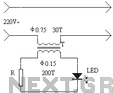
The circuit can be powered directly from the telephone line, utilizing the voltage present (typically between 40 to 50 V) to operate without the need for an external power source. The voltage is sufficient to activate the relay, which is responsible for switching the connection based on the line's status.
When the modem is engaged and the line is active, the circuit remains in a standby state. However, once the modem disconnects, the circuit will trigger an indication, such as an LED light or an audible alert, notifying the user that the telephone line has been released. This feature is crucial for users who rely on their modems for internet connectivity and want to avoid unnecessary charges on their phone bills.
In conclusion, the circuit serves as a practical solution for monitoring telephone line status, ensuring that users are informed about their connection state and can manage their phone usage effectively. The simplicity of the design combined with its effectiveness makes it an ideal choice for individuals who frequently use modems for internet access.The circuit has been designed to accommodate all those who dedicate many hours of their lives by exploring the endless pages of this site. Despite the fact that it consists of only three components (Most were not little!), Is able to provide an indication of whether it actually released the telephone line after a long connection via modem to the network.
This can be particularly useful, since there In many cases, the computer claims that the telephone network connection has been interrupted, but the modem for some reason keeps the line engaged. Symvoulemomenoi indications of this simple circuit you save by unwanted "blocks" of your phone, while ensuring that the end of two months the account will is reasonable. The circuit is based on the specificity of the line to keep a potential that the rest reaches 40 or 50 V.
The same line, that when some conference, 'throw' the trend is sharply to about 1 A n.
Related Circuits
The modulator and demodulator design utilizes an AVR MCU-based program-controlled AFSK modulator due to temperature stability issues with the XR2206 and XR2211 integrated circuits. The modem's size is primarily dictated by the two RCA and DSUB-9 connectors, and while...

Check the loop circuit for an automatic telephone answering system or a tone generator for use in reverse automatic repair. The loop circuit in an automatic telephone answering system is designed to detect incoming calls and activate the answering mechanism....
The installation of an electrical outlet in the refrigerator work light serves to enhance visibility of the refrigerator's interior while also improving the aesthetic appeal of the socket. The circuit is illustrated. Additionally, the circuit utilizes the secondary induced...

This stereo balance indicator circuit diagram is designed using a few common external components. The schematic circuit is very simple to build and will provide a visual indication with LEDs for left, right, and center balance. Outputs from each...
The TCM3105 FSK modem chip from Texas Instruments enables the construction of a modem compatible with Bell 202 or CCITT V23 standards. This modem circuit can transmit data at baud rates of 75, 150, 600, and 1200, and receive...

The following circuit illustrates a UHF Indicator Wavemeter Circuit Diagram. This circuit utilizes dual BF494 transistors. Features: the oscillator is... The UHF Indicator Wavemeter Circuit is designed to measure and indicate the frequency of ultra-high frequency (UHF) signals. The circuit...