
Modified Sine Wave Signal Generator

Pure sine wave inverters are highly regarded for their ability to produce a clean and stable output waveform that closely resembles the natural sine wave produced by utility power. This quality makes them ideal for sensitive electronic devices, such as medical equipment, audio systems, and certain types of motors, which require a smooth and consistent power supply to function correctly. The primary disadvantage of pure sine wave inverters is their higher cost and complexity in design, which can make them less accessible for some users.
Modified sine wave inverters offer a more affordable alternative. They generate a waveform that approximates a sine wave but includes flat tops, leading to a more rectangular shape. While they can efficiently power many household appliances and devices, they may not be suitable for all equipment. Some sensitive electronics may experience issues such as overheating, increased noise, or reduced efficiency when powered by modified sine wave inverters.
Square wave inverters produce a waveform that is purely rectangular, lacking the smooth transitions found in sine wave outputs. These inverters are the least expensive option and are typically used for very basic applications, such as powering simple resistive loads like incandescent light bulbs or heating elements. However, their use with more complex electronic devices can lead to significant operational problems, including inefficiency, potential damage, and increased electromagnetic interference.
In summary, the choice between pure sine wave, modified sine wave, and square wave inverters depends on the specific needs of the equipment being powered, the budget available, and the importance of power quality for the intended application.Pure sine wave inverters are best, however they are expensive to buy or build. Modified sine wave inverters will power some equipment square wave inve.. 🔗 External reference
Related Circuits
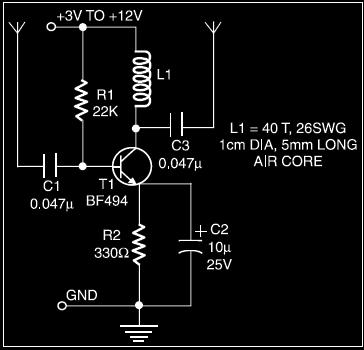
The circuit of an active shortwave antenna enhances weak shortwave signals, allowing for improved clarity when received by a shortwave receiver. The receiver does not need a physical connection; it can be placed within 6 to 7 cm of...
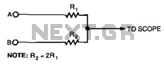
This simple resistor circuit can be used to trick an oscilloscope into displaying two logic signals on one channel. By selecting R2 to be twice the value of R, the oscilloscope trace will show one of four distinct analog...
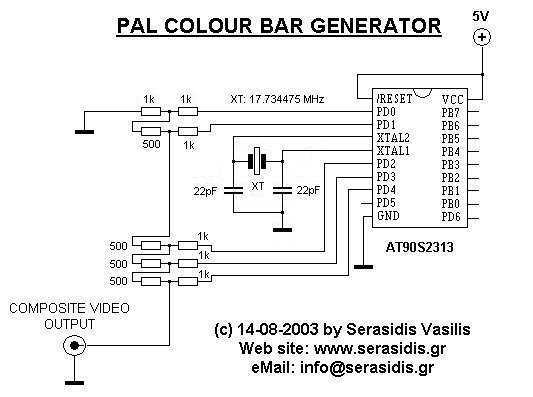
The first idea was to work with an 8.867238 MHz crystal (2 times the color carrier). When reading more about PAL video composite signal creation, it was found that to produce colors entirely in software, one must create the...
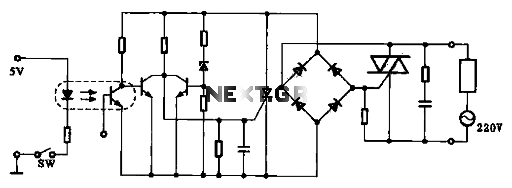
This application example illustrates a photovoltaic control circuit. In this circuit, the Triac functions as a solid-state relay, providing an AC power supply path to the load. It is designed to achieve high current control signals using a small...
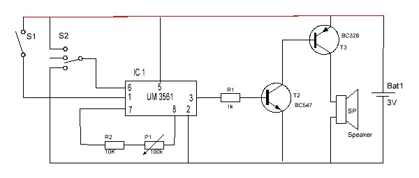
This is a simple audio circuit utilizing the UM3561 for generating melodies that can be employed in toys and various home appliances. It serves as an excellent project for novice beginners. The UM3561 is a dedicated melody generator integrated circuit...
The interval between rings can be adjusted by changing the value of the 1 Meg resistor. A 70 volt, 30 Hz ringing voltage is generated from the 120 volt side of a small 12.6 VAC power transformer (Radio Shack...