
Four-way operation of the reverse brake circuit
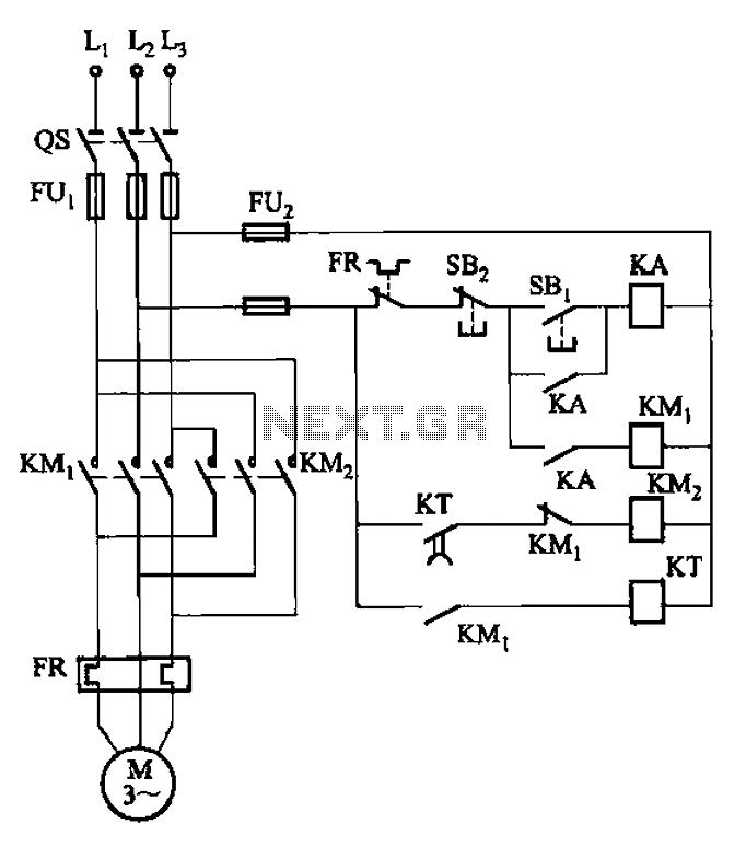
The circuit in question employs a time relay, specifically the KT model, which serves as a critical component for timing control. The adjustable timing range of 1 to 2 seconds allows for flexibility in various applications, enabling the circuit to accommodate different operational requirements. This feature is particularly advantageous in environments where precise timing is essential for functionality.
The use of a time relay instead of a speed relay suggests that the application may involve processes that require a delay before activation or deactivation. This can be crucial in scenarios where dust and other environmental factors may impede the performance of more sensitive components. The design ensures reliability in less-than-ideal conditions, making it suitable for industrial settings or outdoor applications where exposure to contaminants is prevalent.
The circuit likely includes additional components such as resistors, capacitors, and possibly diodes to ensure stable operation and to protect against voltage spikes. Proper selection of these components is essential for maintaining the integrity of the timing function and ensuring that the relay operates within its specified parameters.
Overall, this circuit design represents a robust solution for timing applications in harsh environments, combining adaptability with reliability. Circuit shown in Figure 3-127. It uses the time relay KT instead of the speed relay. Plugging time determined by the KT set. Generally 1-2s (adjustable). The circuit is suitabl e for dusty environment, etc. poor occasions.
Related Circuits
If you need a timer circuit, we go after the most proven 555. However, if the delays are longer, based on timing capacitor capacity is too large. In this case, a circuit of Figure 1 After pressing the button...
This preamplifier is designed to interface with CD players, tuners, tape recorders, and similar devices, providing an AC voltage gain of 4 to drive less sensitive power amplifiers. Given that modern Hi-Fi home equipment often comes with small loudspeaker...
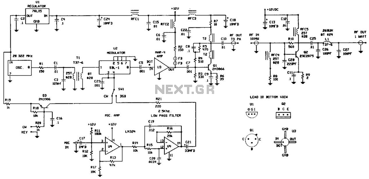
This circuit was detailed in a recent edition of an amateur radio magazine. It enables operation in the 160 to 190 kHz band with a maximum power output of 1 W (license-free) in various modes such as CW, SSB,...
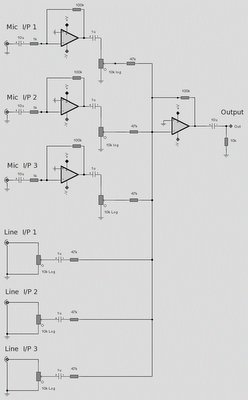
The microphone inputs are amplified approximately 100 times or 40 dB, with the total gain of the mixer, including the summing amplifier, reaching 46 dB. The microphone input is designed for microphones that produce an output of around 2...
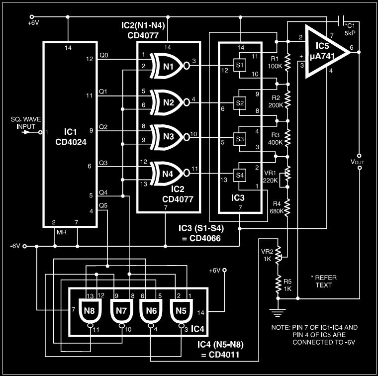
Many electronic devices rely on the shape of signals. Generating square wave signals from sine waves is relatively straightforward, while the reverse process is more challenging. The static square wave-to-sine wave converter circuit can produce an accurate sine wave...
The circuit consists of inverter and charger sections. The inverter section utilizes the NE555 timer, while the charger section is based on the LM317 adjustable regulator. In the inverter section, the NE555 is configured as an astable multivibrator, generating...
Warning: include(partials/cookie-banner.php): Failed to open stream: Permission denied in /var/www/html/nextgr/view-circuit.php on line 713
Warning: include(): Failed opening 'partials/cookie-banner.php' for inclusion (include_path='.:/usr/share/php') in /var/www/html/nextgr/view-circuit.php on line 713