
Modular Music Box

The circuit design involves the integration of a quadrature encoder, which provides two output signals (A and B) that indicate the direction and amount of rotation. The encoder's push button will be connected to a microcontroller, which will utilize the DebounceButton library to handle the button press events reliably. The RSet resistor is crucial for setting the correct current through the LEDs; thus, accurate calculations based on the intended application (individual LEDs versus an LED matrix) are necessary to avoid inconsistencies in brightness and performance.
Incorporating a common ground for the I2C bus is essential for ensuring stable communication between multiple devices. The rotary sequencer box will likely house both the encoder and the necessary circuitry to maintain this common ground. The design must account for the potential contact bounce from the encoder's push button, necessitating software debouncing techniques to ensure that only valid button presses are registered. This will involve implementing additional logic within the microcontroller's firmware to differentiate between actual button presses and noise caused by mechanical bouncing.
Furthermore, attention should be given to the power supply stability and noise filtering, especially in environments where multiple components share the same ground. Capacitors may be employed near the power pins of the microcontroller and the encoder to smooth out any fluctuations. Overall, careful consideration of the components, their specifications, and the interaction between them will lead to a robust and functional design for the intended application.I calculated the RSet resistor value at ~17k though it should probably have been 28k according to the table on the page (the MV7744 data sheet list Vf = 2. 1V and If = 20mA) but that`s for an LED matrix not individual LEDs happy for you to work out what this should be .
Used Keith Neufeld`s Arduino Quadrature Encoder Library available here to download and though initially it didn`t compile reading further in the post I came across instructions to add: Also intending to use quistoph`s DebounceButton Arduino library (link currently not working) to provide onPress(), onRelease, onHold(), onClick() functionality which combined with the push button of the encoder could be useful as a hidden` control system should we need it My colleague Nick discovered the requirements for a common ground for the I2C bus so we`ll need to plan this into the circuitry of one of the boxes probably the rotary sequencer The problem is first that they have a lot of contact bounce and trying to suppress this in software and determine the direction of rotation at the same time is a bit of a big ask and normally it won`t work. I don`t know if you noticed but some times the Project sketch would go in the wrong direction at times.
🔗 External reference
Related Circuits
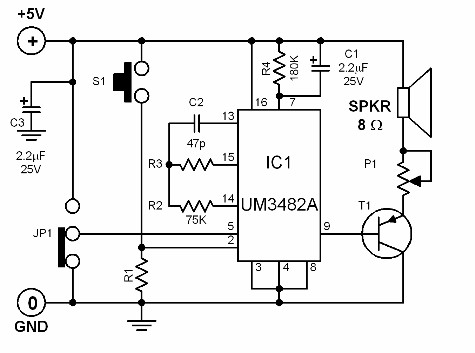
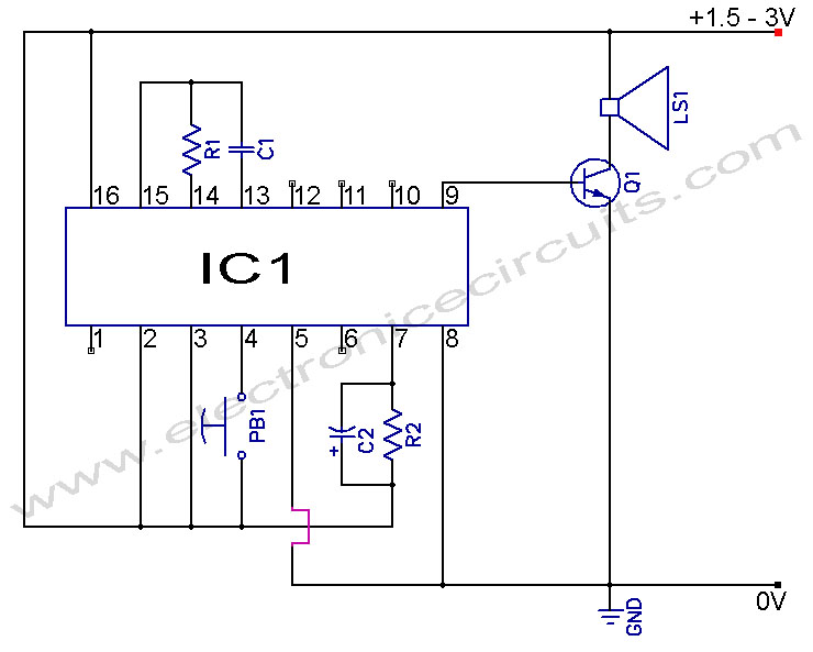
This single-chip module is capable of generating nine distinct melodies. It is typically utilized as a doorbell, an acoustic signaling device, or as a telephone "wait" melody. When switch S1 is activated, the integrated circuit (IC) sequentially plays the...
Musical Doorbell Circuit Diagram. This musical doorbell circuit utilizes the UM3481 A series integrated circuit (IC). It is designed for applications including toys and doorbells. The musical doorbell circuit leverages the capabilities of the UM3481 A series IC, which is...
This circuit incorporates automatic exit and entry delays along with a timed bell cut-off feature. It accommodates both normally-closed and normally-open contacts and includes a 24-hour personal attack/tamper zone. The circuit is permanently connected to a 12-volt supply and...
This circuit generates audio musical notes that can be heard from a distance of up to 10 meters. It consists of two main components: an infrared (IR) music transmitter and an IR music receiver. The IR music transmitter operates...
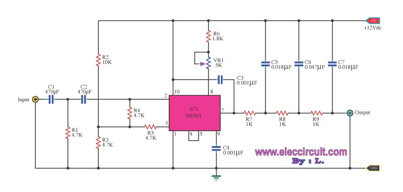
This circuit is a background music (SCA) decoder designed to process an input demodulated (multiplex) FM signal. The NE565, a Phase Locked Loop (PLL) integrated circuit, serves as the foundation for this design. The background music (SCA) decoder circuit utilizes...
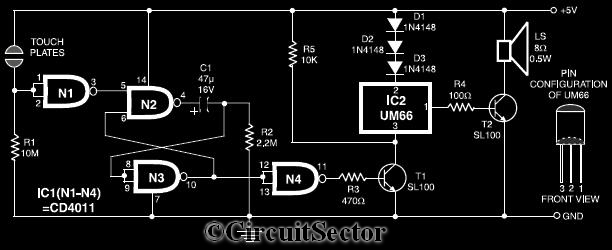
This circuit diagram illustrates a touch-sensitive musical bell based on the UM66 melody generator IC. The design incorporates a CMOS IC CD4011 and features a pair of touch plates. When these plates are briefly bridged by a hand, the...