
Musical Doorbell

The musical doorbell circuit leverages the capabilities of the UM3481 A series IC, which is specifically designed for generating musical tones. The circuit typically consists of a power supply, the UM3481 IC, a speaker, and additional passive components such as resistors and capacitors to shape the audio output.
In operation, the circuit is powered by a low-voltage source, often a battery or a DC power supply. The UM3481 IC receives input signals that can be triggered by a push button or a motion sensor, which activates the musical sequence. This IC is capable of producing a variety of tones and melodies, making it suitable for use in doorbells, where a pleasant sound is desired to alert homeowners of visitors.
The output of the UM3481 is connected to a speaker, which converts the electrical signals into audible sound. The circuit may also include a volume control feature, allowing users to adjust the loudness of the sound produced. Additionally, filtering capacitors may be used to smooth out any fluctuations in the power supply, ensuring a consistent audio output.
Overall, this musical doorbell circuit provides an engaging and functional solution for alerting users, enhancing the traditional doorbell experience with musical tones. The design is straightforward, making it accessible for hobbyists and engineers looking to implement a creative audio signaling system in various applications.Musical Doorbell Circuit Diagram This musical doorbell circuit uses UM3481 A series IC. It is intended for applications such as toys, door.. 🔗 External reference
Related Circuits

It is a wireless doorbell with a cost of about $10.00. This product encourages a shift in approach to building projects, utilizing such items to learn about their functions and modify them to meet specific needs. The doorbell incorporates...

In all the houses exist the bells in the door. All want, they have the possibility of being possible to change the intensity, the tone of sound. With this circuit we have this possibility. With the materials round the...
.jpg)
The project outlines a method to add a cost-effective remote doorbell to an existing household doorbell system, particularly useful for individuals who may not hear the doorbell when in the basement. The household doorbell operates on a continuous 24VAC...
Adding this combination audio circuit, as illustrated in figure 14-38, to the automatic rhythm generator of electronic musical instruments fulfills the players' demand for incorporating drum and cymbal audio, enhancing the overall performance effect. The diagram indicates that the...
It is easy to miss the sound of a doorbell while watching TV. This circuit addresses the issue by providing a visual indication, such as a lamp or an LED. Connecting a lamp directly in parallel with the doorbell...
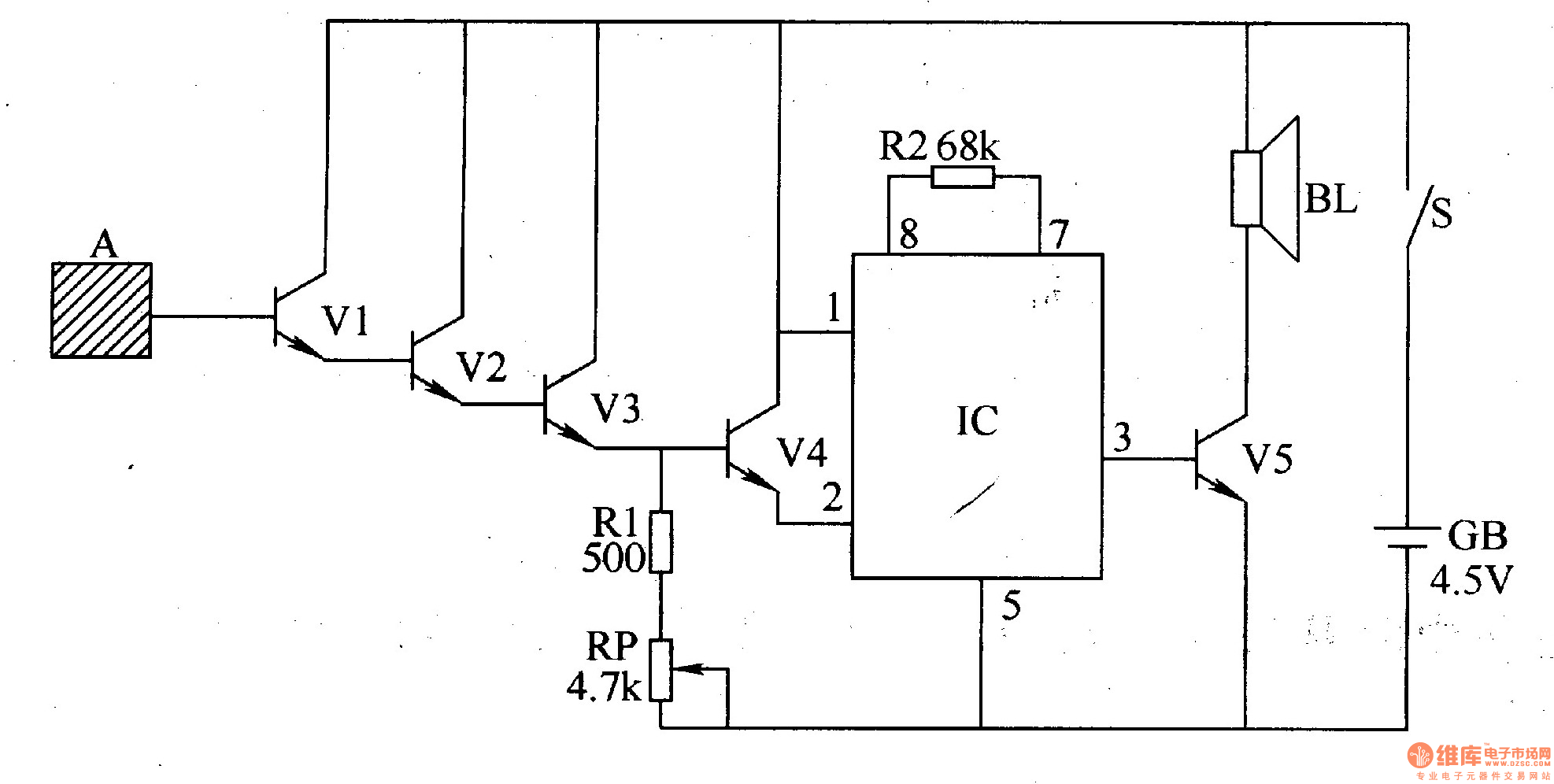
The inductive electronic doorbell circuit consists of an inductive electronic switch and a music generator circuit, as illustrated in Figure 3-115. The inductive electronic switch circuit includes an inductive electrode A, transistors V1-V4, a resistor R1, and a potentiometer...