
momentary button as onoff toggle using 555

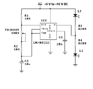
The circuit utilizes the 555 timer in a monostable configuration, where the timer is triggered by pressing a button. The output from the timer is connected to the base of the 2N3904 transistor, which acts as a switch for the connected load. The 555 timer's pin configuration is critical: pin 1 is connected to ground, pin 2 is the trigger pin, pin 3 is the output pin connected to the transistor base, pin 4 is the reset pin, pin 5 is connected to ground through a capacitor for stability, pin 6 is the threshold pin, and pin 7 is the discharge pin. The timing components, typically a resistor and capacitor, determine the duration for which the output remains high after the button is pressed.
The suggested modifications for ensuring the circuit defaults to the Off state include the addition of the resistor and capacitor at pin 4, which helps to reset the timer upon power-up, preventing any erratic behavior of the LED. The circuit can be further enhanced by integrating an infrared (IR) receiver, such as the TSOP1838, allowing for wireless activation. This would involve connecting the output of the IR receiver to the trigger pin of the 555 timer, enabling remote control of the load.
Overall, this circuit design is flexible and can be adapted for various applications by changing the transistor type to accommodate different load requirements, making it suitable for both small and larger electronic projects. Proper attention to component selection and configuration will ensure reliable operation and enhance user experience in applications requiring remote switching capabilities.Most all work off of some flip-flop like principle. And while I could have suggested a true flip-flop chip, I thought it would be cooler if you could use a 555 timer chip (which contains a single flip-flop and a couple of comparators). After scouring my childhood collection of Forrest Mims electronics books and a few 555 timer devoted websites (two of the best I found were: & ), I cobbled together the following circuit based off a few almost-what-I-wanted examples. The parts cost is pretty low. The 555 timer chip can be had for about $0. 43, the 2N3904 transistor for ~$0. 40, and various resistors & capacitors are essentially free if you have them. The circuit has 3 external two-pin connections: 5V&Gnd, button input, and the two pins of the thing to switch.
In this case, the switched thing is a power supply to a BlinkM. By changing the transistor to a beefier one, you can switch much larger loads. The little 2N3904 transistor in there now can switch around 200mA, but a bigger NPN or FET transistor and you could switch a few amps. It`s not the greatest for battery-powered applications. When off it draws about 4-6mA, depending on the brand of 555 timer chip you use. When on it draws that plus whatever power the switched device draws. Best to put a proper power switch on the battery pack to eliminate this quiescent drain. I was wondering, do you know of a way to make sure the circuit is always defaulting to Off when you power it up I have the circuit working, but when I initially turn on the power supply I get the LED on sometimes and off sometimes, even though I have been making sure the circuit is in the off position when I power it down.
I`d like this as a safety feature, but I lack the insight into that problem. Thanks in advance for any information and thanks for posting this. As a newbie I really needed to see the circuit in another form besides the schematic to make heads or tails out of it. Disconnect pin 4 from +5V. Put a 10K resistor from pin 4 to +5V and a 0. 1uF capacitor from pin 4 to GND. That will give the circuit a short reset pulse when power is applied. I`m a beginner, and doing an ardiuno project. for the project I needed 12v (for the arduino) 5V for a relay and 3. 3 for a lcd screen backlight. so I ended up using a ATX power supply. Hi there. this circuit is very nice. and easy to build with your instructions im trying to activate this, with one IR tsop1838 (so it will be wireless :P ) and one transistor doing the job as switch.
but i got stuck i can activate the led but i cant deactivate it xD I`ve found the solution for this circuit. With only a few modifications in the schematic diagram it`s possible to correct the problem of the self-shoot on the output when connecting or disconnecting the power supply, no matter how the circuit is powered, either an AC/DC adapter or a battery.
🔗 External reference
Related Circuits

The Spartan-3an board features eight slide switches, as illustrated in the accompanying figure. The push button inputs are typically in a low state and transition to a high state only when the button is pressed. These push buttons are...

The circuit illustrated in the figure is a dimmer using the 555 timer as the core component. The 555 timer, along with resistors R1, RP, R2, and capacitor C1, forms an astable multivibrator. The oscillation frequency, f, is calculated...
A thermistor is utilized in the circuit for heat sensing, while two 5K variable resistors are incorporated to calibrate the circuit for activating the relay at the desired temperature. The inclusion of a 1N4007 diode across the relay serves...
Power pulse circuit using LM350 and NE555. This circuit can be used to drive lamps, power LEDs, DC motors, etc. Adjust R5 for output amplitude and R1 for output power. The LM350 is an adjustable 3-terminal voltage regulator. The power...
This is a simple LED flasher project that utilizes a common 555 timer integrated circuit (IC) for its operation. It is configured in astable mode, which means its output functions as a square wave oscillator. Two LEDs are connected...
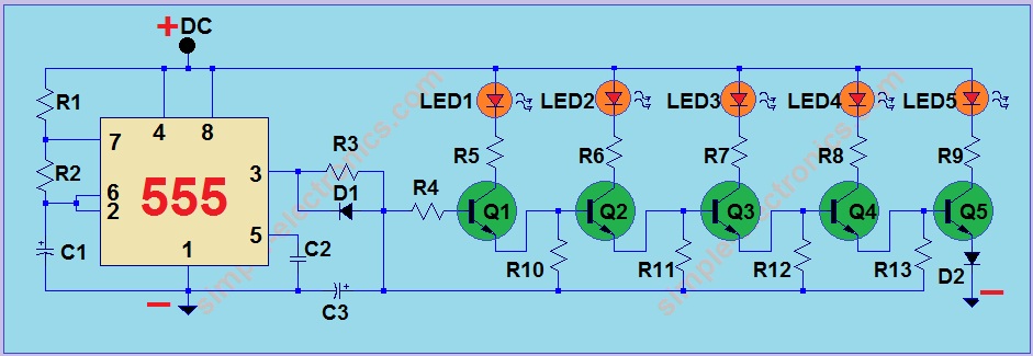
This project utilizes a 555 integrated circuit (IC) to create a sequential LED flashing effect. The configuration allows the LEDs to illuminate in a specific order, making it suitable for use as an indicator for vehicles and bicycles when...