
push button interfacing with spartan 3an fpga

The Spartan-3an board is designed to facilitate various input configurations through its eight slide switches and push button inputs. Each slide switch can be used to represent binary states, allowing for easy manual input of control signals. The push buttons, when activated, provide a momentary high signal to the FPGA, enabling it to respond to user interactions.
The push button inputs are connected to the FPGA's I/O lines, which are configured to detect the state changes. When a push button is pressed, the corresponding I/O line transitions from low to high, which can be used to trigger specific functions or processes within the FPGA. This functionality is critical for applications requiring user input, such as in development and testing environments.
In terms of circuit design, it is important to incorporate pull-down resistors for the push button inputs to ensure that the I/O lines remain in a defined low state when the buttons are not pressed. This prevents floating states that could lead to unpredictable behavior. The slide switches can similarly be connected with pull-up or pull-down resistors, depending on the desired logic level when the switch is in the off position.
Overall, the Spartan-3an board's input interface is versatile, allowing for a range of applications from simple user controls to complex signal processing tasks, making it a valuable tool for engineers and developers in the field of electronics.The Spartan-3an board has eight slide switches, indicated as in Figure. Push button inputs are normally low and driven high only when the push button is pressed. Push Buttons are interfaced with FPGA I/O lines. 🔗 External reference
Related Circuits
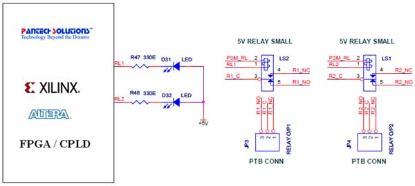
The Universal Development Board features external 5V relay interfacing, as illustrated in the accompanying figure. The ULN2803 is utilized as a driver for FPGA I/O lines, with the driver outputs connected to the relay modules. A PTB connector is...
This article discusses practical techniques for incorporating "correctness by design" in DDR2 interfaces from a Signal Integrity (SI) perspective, utilizing the current generation of available design tools. It analyzes common DDR2 design errors and the trade-offs between various popular...
This article outlines a reliable, straightforward, and universal method for interfacing Motorola mobile radios from the MaxTrac, Radius, and GM300 series with common repeater controllers. The information provided is also relevant for radio interfaces used in IRLP or EchoLink...
Microchip has addressed the need for memory solutions with a comprehensive range of serial EEPROMs, available in various memory configurations and utilizing standard 2- or 3-wire communication protocols. The following assembly code outlines the procedure for writing and reading...
You may find that there are too few, if your power is very noisy (as can happen in a car environment) it may help to place a 0.1uF and/or 10uF capacitor before and/or after the voltage regulator. At the...
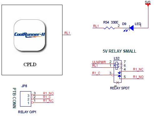
The CoolRunner-II board features external 5V relay interfacing, as indicated in the accompanying figure. The ULN2803 is utilized as a driver for the CPLD I/O lines, with the driver outputs connected to the relay modules. A PTB connector is...