
Monitoring by the pulse signal constituting the single-shot generating circuit

The pulse generating circuit operates on the principles of monostable multivibrators, commonly referred to as monostable flip-flops. This circuit is designed to produce a single output pulse in response to a triggering input signal. The operation begins when the input voltage (V1) exceeds a certain threshold, causing the circuit to transition from its stable state to a temporary unstable state, during which it generates a pulse.
The output of the monostable flip-flop (V0) is characterized by a specific duration determined by the circuit's timing components, typically a resistor-capacitor (RC) network. The timing is crucial as it defines the width of the output pulse (QA), which can be adjusted by varying the values of the resistor and capacitor in the circuit.
In practical applications, the pulse generating circuit can be used in various timing and control applications, such as generating clock pulses for digital circuits, debouncing mechanical switches, or creating specific time delays in electronic systems. The waveform of the input and output signals can be analyzed using an oscilloscope, where the input signal (V1) will show a sharp transition, while the output signal (V0) will display a pulse of defined width corresponding to the circuit's configuration.
The design considerations for such circuits include the selection of the appropriate components to ensure reliable operation across the desired range of frequencies and pulse widths. Additionally, the stability of the circuit can be enhanced by incorporating hysteresis, which prevents false triggering from noise in the input signal.by the pulse generating circuit monitor signal monostable flip-flops Monitoring by the pulse signal constituting the single-shot generating circuit Pulse generating circuit shown in formula a key signal from the monostable flip-flops. Its input (vl) and output (Vo, QA) signal waveform shown in FIG.
Related Circuits
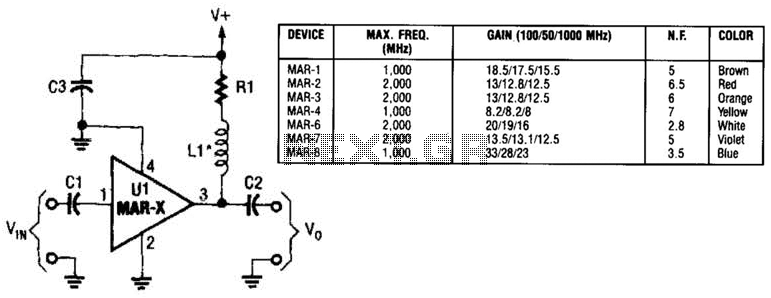
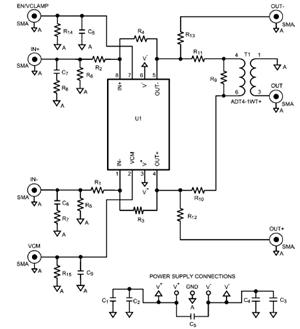
In this basic MAR-x-based circuit, both the input and output consist of a single DC-blocking capacitor (C1 for the input and C2 for the output, respectively). The DC power supply network, which includes L1 and R1, is connected to...
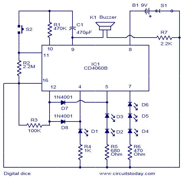
This is a simple and easy-to-construct digital dice circuit. The circuit is based on a single IC, CD4060B. The dice consists of six LEDs marked D1 to D6. The number of LEDs glowing indicates the numeral. The heart of...
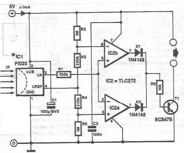
This infrared detector circuit is designed using the PID20 integrated circuit manufactured by Siemens, which converts thermal radiation into electrical impulses. It includes an operational amplifier and several electronic components. The output signal at pin 3 is compared with...
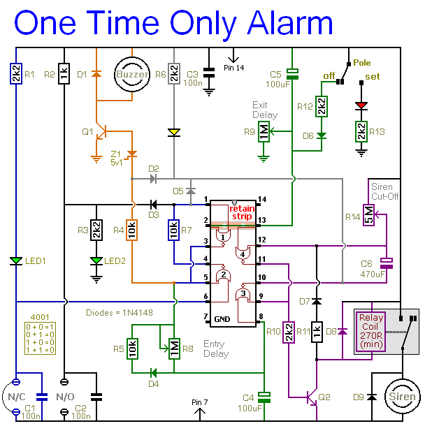
This alarm is designed to activate its siren only once. When the alarm is triggered, the siren will sound for a predetermined duration before automatically turning off and remaining inactive. The alarm system features a single zone with independently...
The transmitter's function is to modulate the original signal frequency of the message-carrying signal, a process known as modulation. The circuit realization of this function is referred to as a frequency modulation (FM) circuit. FM tuners are categorized into...
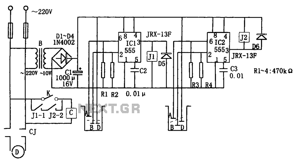
The level control circuit comprises a step-down rectifier circuit, a trigger circuit utilizing two 555 timer ICs (IC1 and IC2), and a relay control circuit. The rectifier circuit is responsible for providing the necessary DC voltage for the flip-flop...