
Rf Preamplifiers Circuit

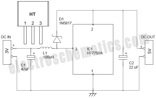
The MAR-x circuit configuration utilizes two crucial DC-blocking capacitors, C1 and C2, which serve to prevent any DC voltage from affecting the subsequent stages of the circuit while allowing AC signals to pass. The input capacitor, C1, is positioned at the input stage to filter out any DC components present in the incoming signal, ensuring that only the desired AC signal is processed by the MAR-x device. Similarly, the output capacitor, C2, performs the same function at the output stage, allowing for the clean transmission of the AC signal to the next stage of the circuit without any DC offset.
The power supply network, consisting of an inductor (L1) and a resistor (R1), plays a critical role in providing the necessary DC voltage and current to the MAR-x. The inductor L1 is typically chosen to provide a stable current supply while minimizing any potential ripple that could affect performance. The resistor R1 may be used for current limiting or to provide a specific load to the circuit, ensuring that the MAR-x operates within its specified parameters.
The connection of the power supply network to the MAR-x via the RF output terminal (lead 3) is essential for proper operation. This connection allows the MAR-x to receive the necessary power while also facilitating the transfer of the RF signal, which is critical for the overall functionality of the circuit. Proper attention must be given to the layout and component selection to ensure optimal performance and reliability of the MAR-x circuit. In this basic MAR-x-based circuit, both the input and output are comprised of a single dc-blocking capacitor (CI and C2 for the input and output, respectively). The dc power-supply network (comprised of LI and Rl) is attached to the MAR-x via the RF-output terminal (lead 3).
Related Circuits

This circuit allows for the observation of movement between various stroboscopes. The generation of a rectangular signal is accomplished using an NE555 timer. It operates on a low power supply, which is created using a simple transformer (TR1), a...

A regenerative radio operates by feeding back a small portion of the amplified output from the detector into the input. This feedback mechanism enhances sensitivity significantly beyond what a detector can achieve on its own. The simple regenerative radio...
There are several methods to convert an AC voltage from a wall receptacle into the DC voltage required by a microcontroller. Traditionally, this has been accomplished using various types of power supply circuits. To convert AC voltage to DC voltage...
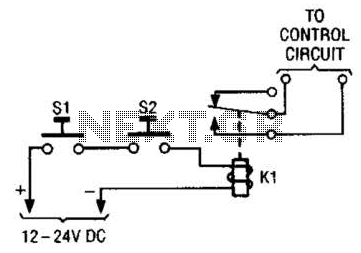
The simple two-hand safety control switch consists of two pushbutton switches connected in series; both must be depressed to energize the relay. The two-hand safety control switch is designed to enhance safety in applications where the operation of machinery or...
This circuit is a small +5V power supply, which is useful when experimenting with digital electronics. Small inexpensive wall transformers with variable output voltage are available from any electronics shop and supermarket. Those transformers are easily available, but usually...
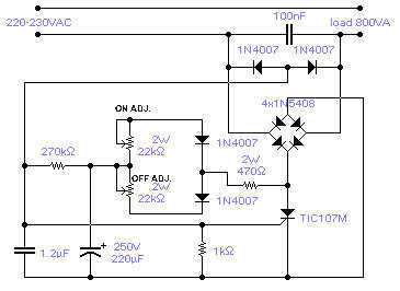
The circuit shown will switch on and off a resistive or inductive load up to 800VA with the possibility to adjust both the on and off period. Switching takes place during the zero crossing of the sine wave. The...