
MOS FET inverter

FETs are semiconductor devices that control the flow of current using an electric field. Due to their high input impedance and low output impedance, FETs are well-suited for linear amplification applications. In a linear amplifier configuration, the FET operates in the active region, where it can amplify small input signals. The output signal is a scaled version of the input, maintaining the waveform shape, which is essential for audio and RF applications.
In addition to their role in amplification, FETs can be employed in digital circuits as logic gates. For example, a simple inverter can be constructed using a single FET. In this configuration, when the input voltage is high, the FET turns on, allowing current to flow from the drain to the source, resulting in a low output voltage. Conversely, when the input voltage is low, the FET turns off, and the output voltage becomes high. This basic principle can be expanded to create more complex logic gates such as NAND and NOR by combining multiple FETs in various configurations.
Overall, FETs serve dual purposes in electronic design, facilitating both analog signal processing through amplification and digital signal processing through logic gate implementation. Their versatility makes them integral components in modern electronic circuits.FET can be used as a linear amplifier, a logic gate circuit may also be made,
Related Circuits
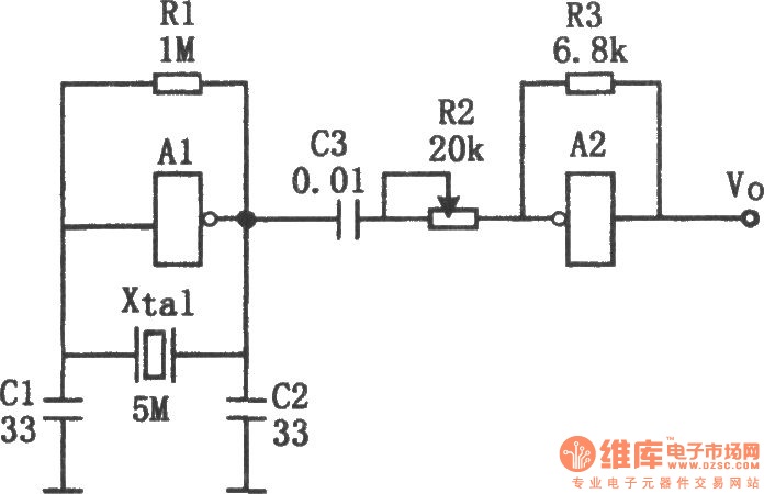
The sine wave generator composed of an inverter is illustrated in the chart. This circuit can produce a high-stability sine wave at frequencies exceeding a few megahertz. In the diagram, A1 and the crystal oscillator create an oscillating circuit,...
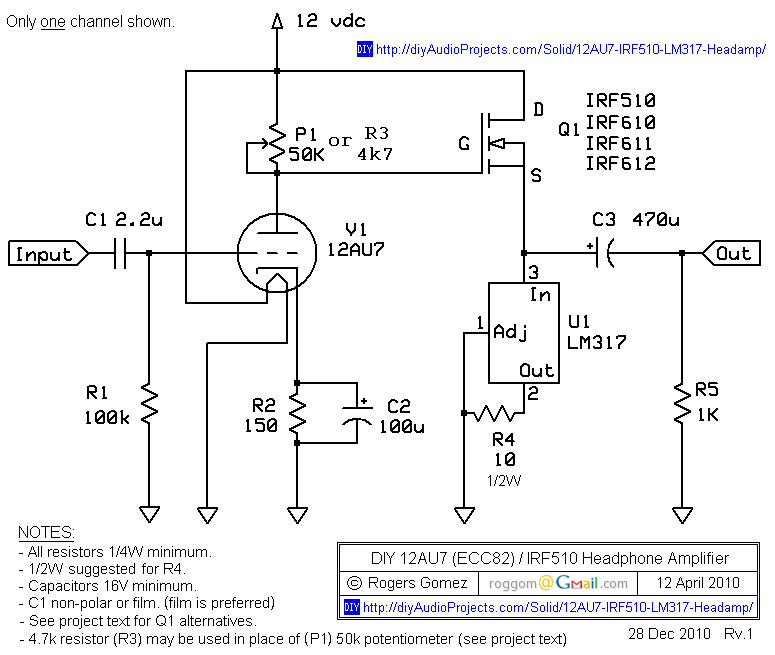
The NP-100v12 is a straightforward headphone amplifier designed for entry-level builders to assemble and listen to their own creation. The term "builder" refers to individuals with electronic experience and innovation, allowing them to create a device rather than merely...
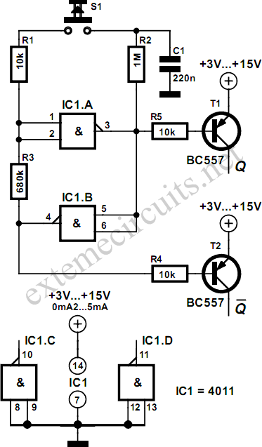
Using just two NAND or inverter gates, it is possible to build a D-type (or toggle) flip-flop with a push-button input. At power-up, the output of gate N2 is at a logical 1, ensuring that transistor T2 is switched...

Using just two NAND or inverter gates, it is possible to build a D-type (or toggle) flip-flop with a push-button input. At power-up, the output of gate N2 is at a logical 1, ensuring that transistor T2 is switched...
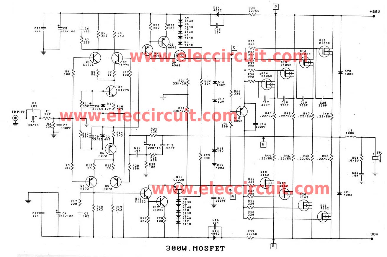
When an amplifier with high watt power is required, this circuit is most suitable for applications such as concerts, theaters, and festivals. This high-power amplifier circuit is designed to deliver significant output power, making it ideal for large-scale audio applications...
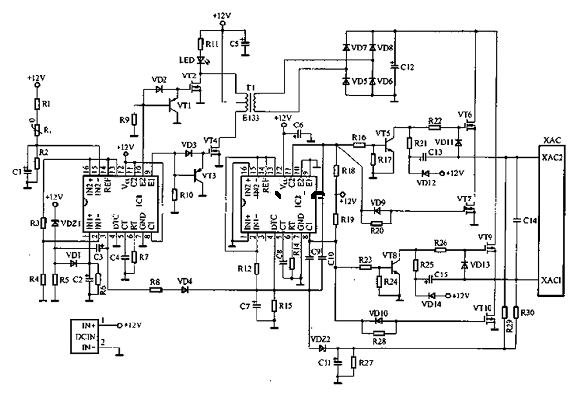
A common car inverter circuit and its working principle. Car inverter specifications include: Input voltage: DC 10V to 14.5V; Output voltage: AC 200V to 220V with a tolerance of 10%; Output frequency: 50Hz with a tolerance of 5%; Output...