
Mosfet TESTER

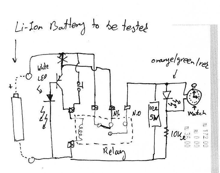
The described circuit employs an astable multivibrator configuration, which is a type of oscillator that continuously switches between its high and low states, producing a square wave output. In this setup, the MOSFET acts as a switching element that controls the operation of the LED. When the MOSFET is functioning correctly, it allows current to flow through the LED, causing it to flash at a frequency determined by the timing components of the multivibrator.
The astable multivibrator circuit typically consists of a pair of resistors and a capacitor connected to a voltage source and the MOSFET. The resistors set the charge and discharge times of the capacitor, which in turn determines the flashing rate of the LED. The MOSFET is integrated into the circuit to provide efficient switching, allowing the LED to be turned on and off rapidly without significant power loss.
It is important to note that the circuit's ability to test MOSFETs is limited. While it can indicate whether a MOSFET is operational by observing the LED's behavior, it does not diagnose all potential failure modes or conditions that may affect the MOSFET's performance. Therefore, this circuit serves primarily as a basic visual indicator of MOSFET functionality rather than a comprehensive testing solution. Proper testing of MOSFETs may require more sophisticated equipment and methods to assess parameters such as threshold voltage, on-resistance, and switching characteristics.I dont claim circuit can test all bad mosfets or all fault mosfet conditions. If mosfet is working it will operate in the astable multivibrator circuit causing the Led to flash. 🔗 External reference
Related Circuits
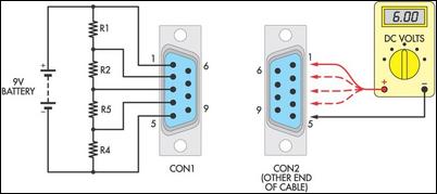
Many cable testers have been previously published, some of which are quite complex. However, here is a cost-effective and straightforward alternative. It utilizes only a 9V battery, two mating connectors, and several resistors, along with a multimeter for voltage...
It is assumed that individuals interested in constructing this circuit can interpret the schematics provided below. Basic principles: Note that lithium-ion batteries should not be discharged below 3V. The circuit design focuses on the safe operation of lithium-ion batteries, particularly...

Q1 functions as a Colpitts crystal oscillator. If the crystal being tested is operational, the RF signal is rectified by diodes D1 and D2, which activates Q2 and illuminates indicator LED2. Additionally, LED1 serves as a power indicator. The circuit...

Assistance is required for a final year project involving the design of a grid-connected inverter. The focus is on developing a full bridge inverter circuit. The grid-connected inverter is a crucial component in renewable energy systems, particularly in solar photovoltaic...

Sur ce site, il est possible de trouver des contributions dans des domaines d'intérêt variés. Il est également possible de suivre l'auteur sur Twitter : @davbucci. Le site est constitué de contributions hétérogènes. L'accès se fait via les liens...
This circuit utilizes a single 555 Timer IC and a small transformer to generate high voltage for testing zener diodes with voltage ratings up to 50VDC. The 555 Timer is configured in astable mode, with the output from pin...