
Li-Ion Battery capacity tester

The circuit design focuses on the safe operation of lithium-ion batteries, particularly emphasizing the importance of maintaining a minimum voltage threshold to prevent damage. Lithium-ion batteries are widely used due to their high energy density and rechargeability; however, they require careful management to ensure longevity and safety.
The schematic includes a battery management system (BMS) that monitors the voltage levels of the lithium-ion cells. This system typically consists of a microcontroller that continuously checks the voltage of each cell. If the voltage drops below the critical threshold of 3V, the BMS will disconnect the load from the battery to prevent over-discharge.
Additionally, the circuit may incorporate a series of resistors and comparators to provide feedback to the microcontroller, allowing for precise voltage measurements. Capacitors may also be included to filter noise and stabilize the voltage readings.
Furthermore, the design could feature LED indicators that visually represent the status of the battery, such as charging, discharging, or low voltage conditions. This enhances user awareness and promotes safe handling of the battery pack.
Overall, the schematic aims to ensure that lithium-ion batteries are operated within safe parameters, thereby maximizing their lifespan and performance while minimizing risks associated with improper usage.I assume anyone who wants to make this can read the schematics bellow Basic principles:NOTE:Li-Ion batteries shouldn`t be discharged bellow 3V (In.. 🔗 External reference
Related Circuits
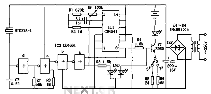
The CD4001/CD4541 nickel-cadmium battery automatic charger circuit is illustrated in the figure. This circuit is designed for charging up to seven rechargeable nickel-cadmium batteries. It features automatic charging with constant current characteristics. Once powered, the circuit activates an internal...
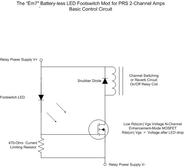
For individuals seeking LED-based footswitching without the inconvenience of battery installation, a battery-less LED-based footswitch modification is being developed for 2-channel amplifiers. This solution is designed to work with the existing TRS jack and footswitch, and it will involve...
The operating principle of the circuit is very simple. The first LED D1 is placed in series with the resistor R2 and diode D4. An only be lit this LED indicates that the battery is overcharged. For this reason,...
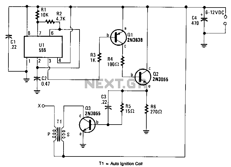
An output voltage sufficient to bridge a one-inch gap can be generated from a 12-V power source. A 555 timer integrated circuit (IC) is configured as an astable multivibrator, producing a narrow negative pulse at pin 3. This pulse...
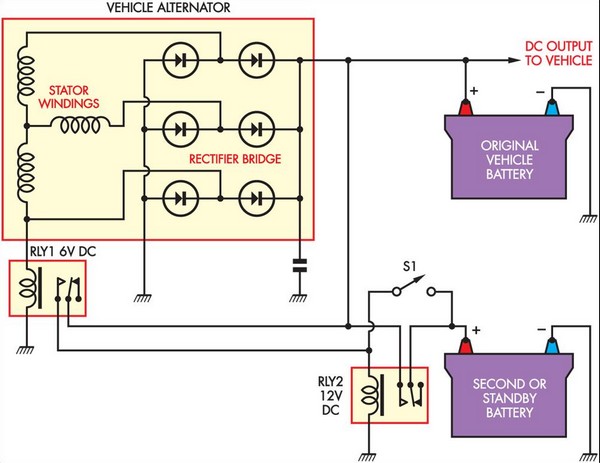
This circuit is straightforward and utilizes a 6V supply from one of the stator connections of the vehicle's alternator. This supply is connected to a 6V automotive relay (RLY1), which controls a Continuous Duty Solenoid (RLY2). The solenoid serves...
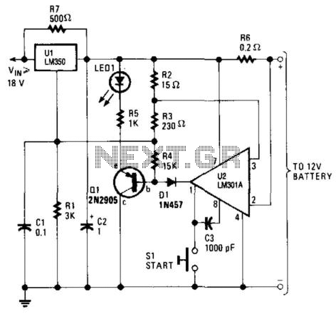
This high-performance charger efficiently charges gelled lead-acid batteries and automatically shuts off upon reaching a full charge. Initially, the charging current is maintained at 2 A; however, as the battery voltage increases, the current gradually decreases. Once the current...